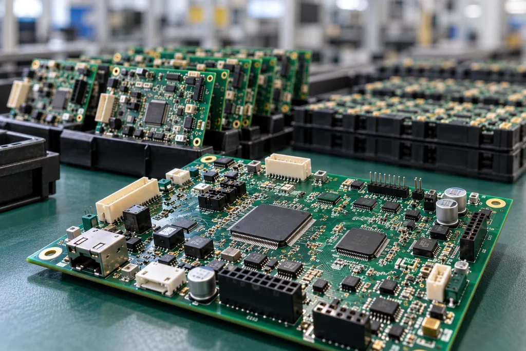
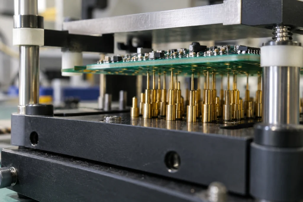
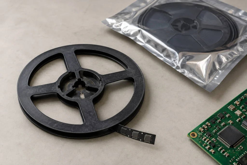
Phase 1
Pre-Production & Engineering
- 01 BOM Review
- 02 DFM / DFA Review
- 03 PCB Fabrication
- 04 Wave Soldering Pallet (ESD-Composite) Customization
Rather than re-stating elementary electronics definitions, we define Through-Hole Technology (THT) by its critical engineering function: the insertion of component leads directly into Plated Through-Holes (PTH) on a rigid board, followed by wave or selective soldering to establish a high-strength metallurgical bond. While surface-mount devices (SMD) handle high-density logic circuits, THT remains irreplaceable for components exposed to repetitive mechanical stress, thermal cycling, or high electrical currents. To ensure versatile manufacturing execution, our assembly workflows seamlessly accommodate both axial and radial passive configurations — such as resistors, capacitors, and diodes prepared via automated lead-forming machines — as well as multi-pin Dual In-line Packages (DIP ICs, optocouplers), shrouded board headers, industrial relays, and heavy-duty terminal blocks that demand absolute physical insertion stability.
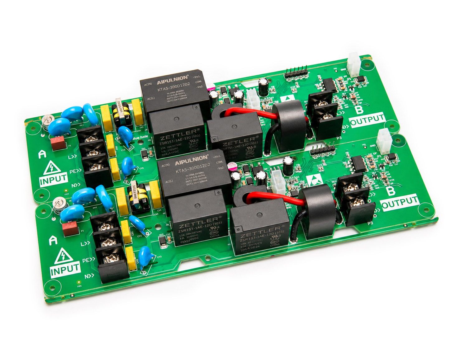 Relay and Magnetics THT/DIP Assembly
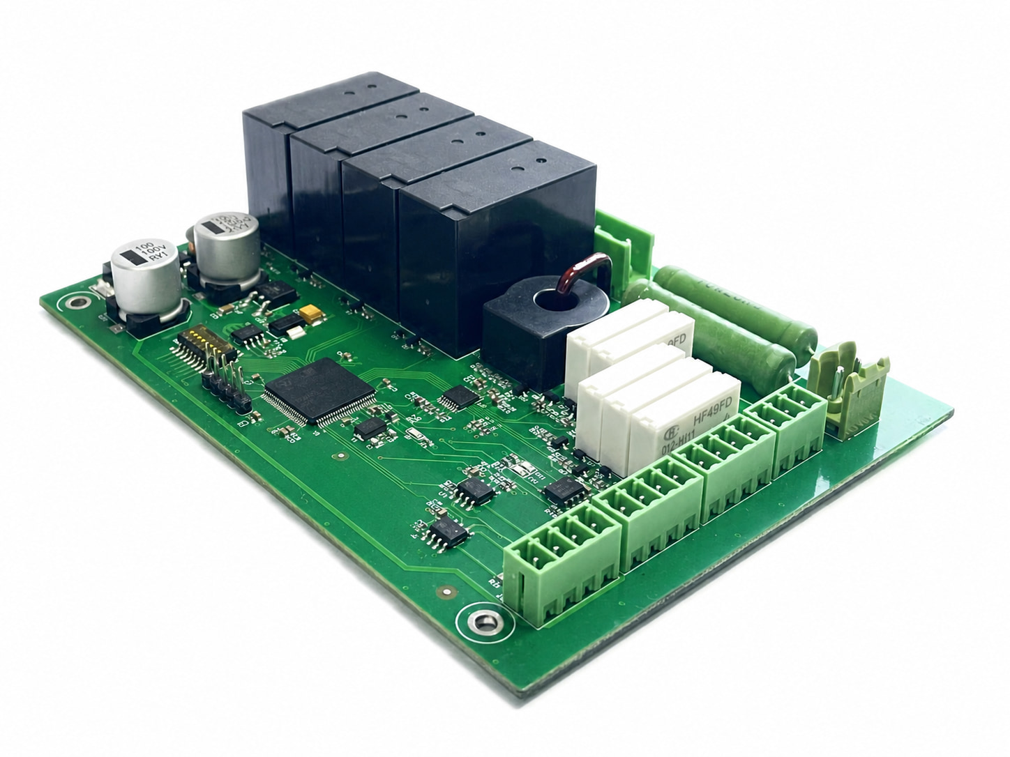 Terminal-Block THT/DIP Assembly
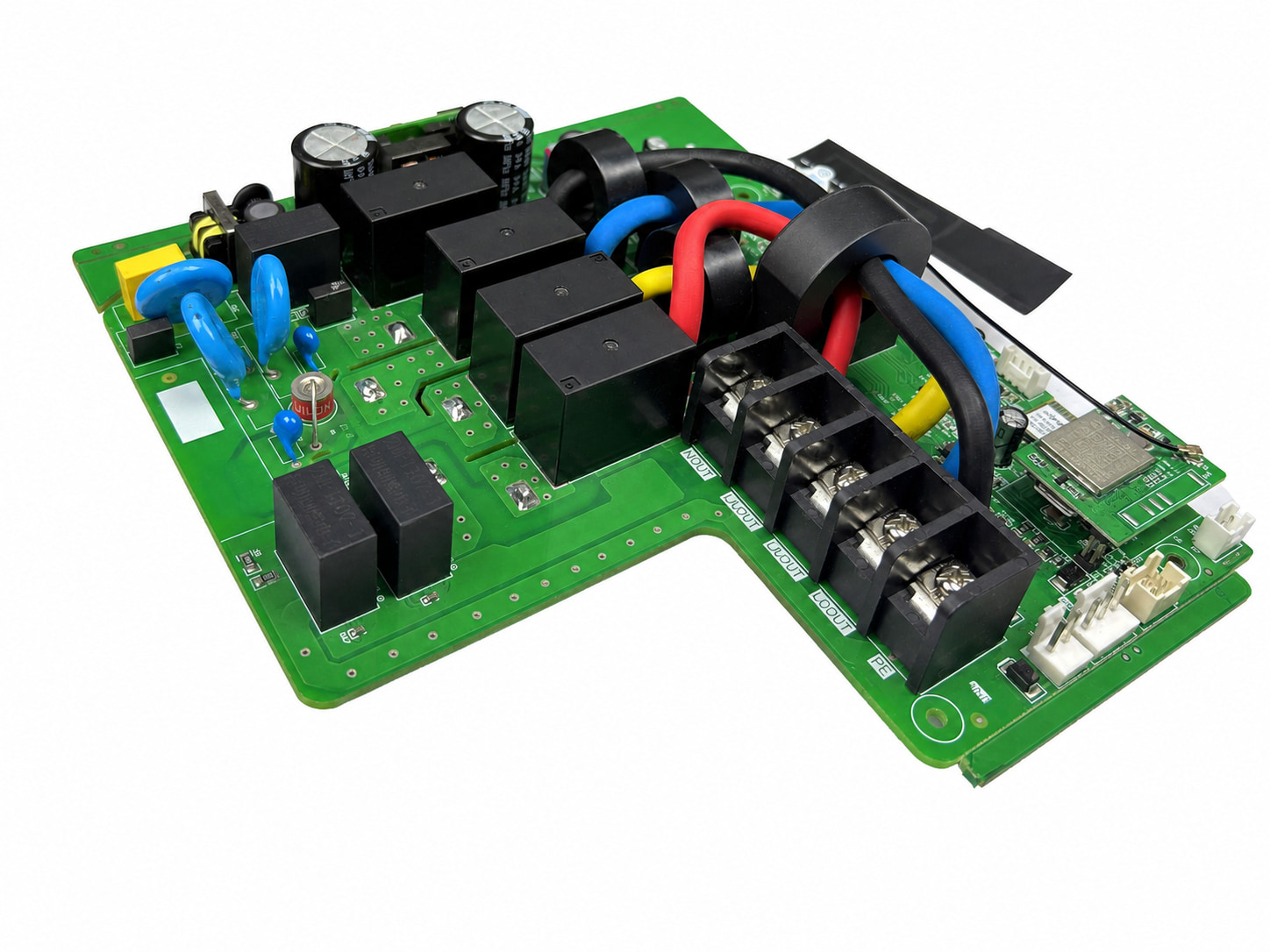 THT/DIP Assembly with Wiring and Terminals
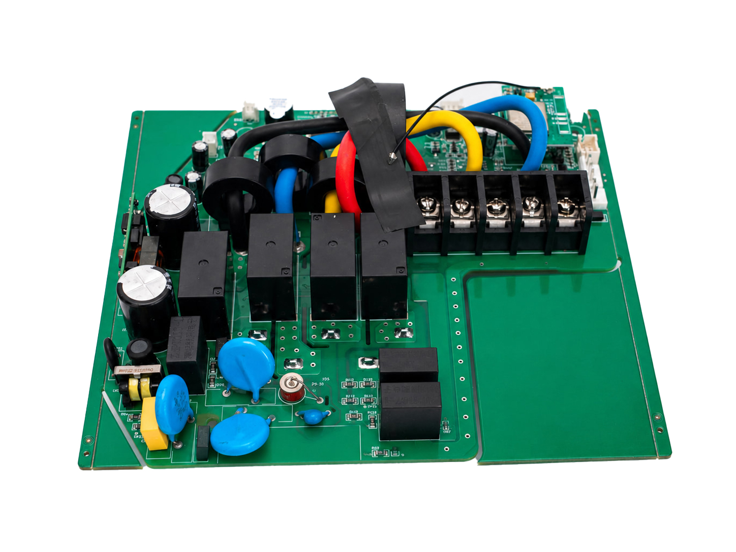 Power-Component THT/DIP Assembly
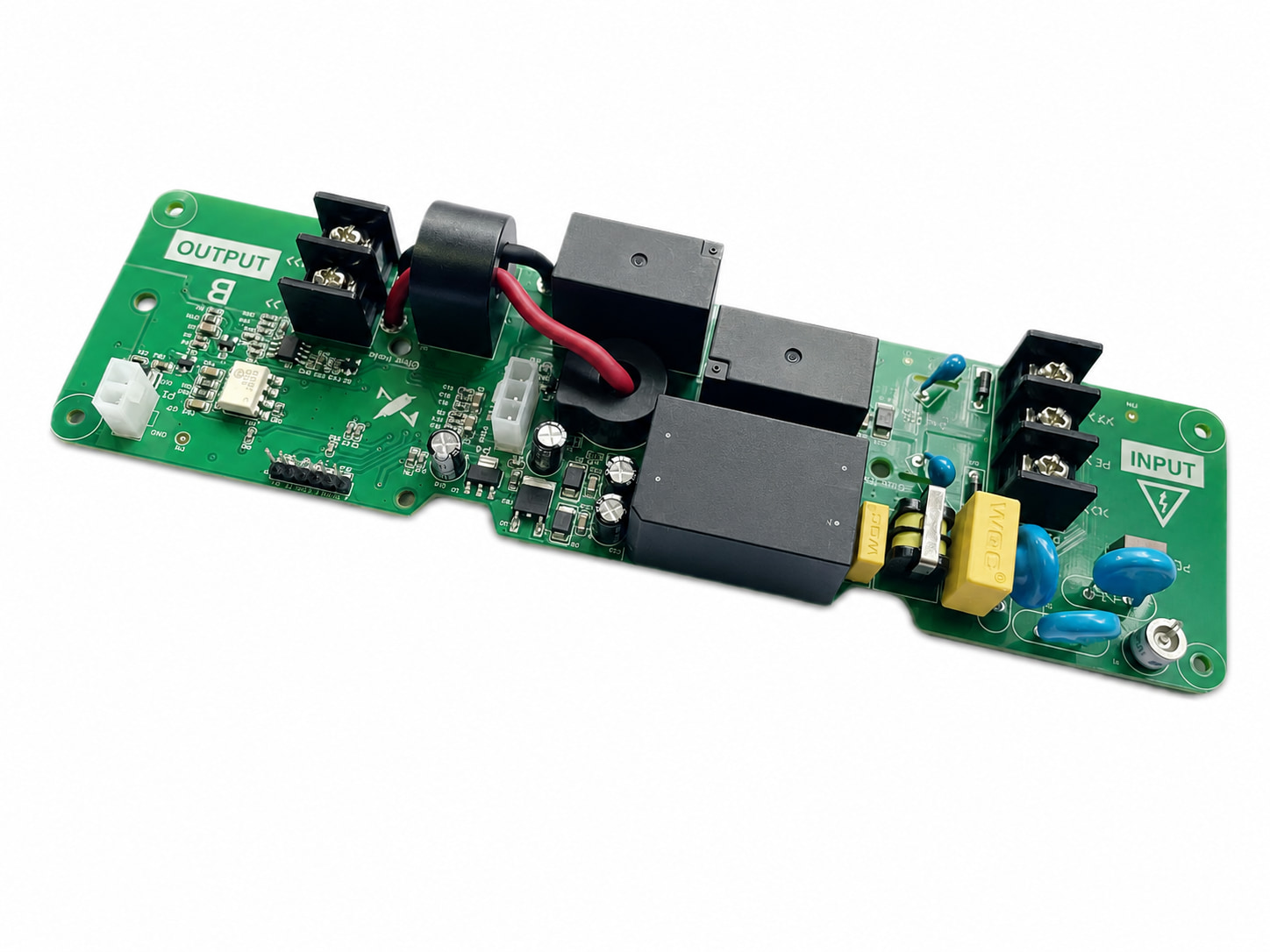 Long-Format THT/DIP Assembly
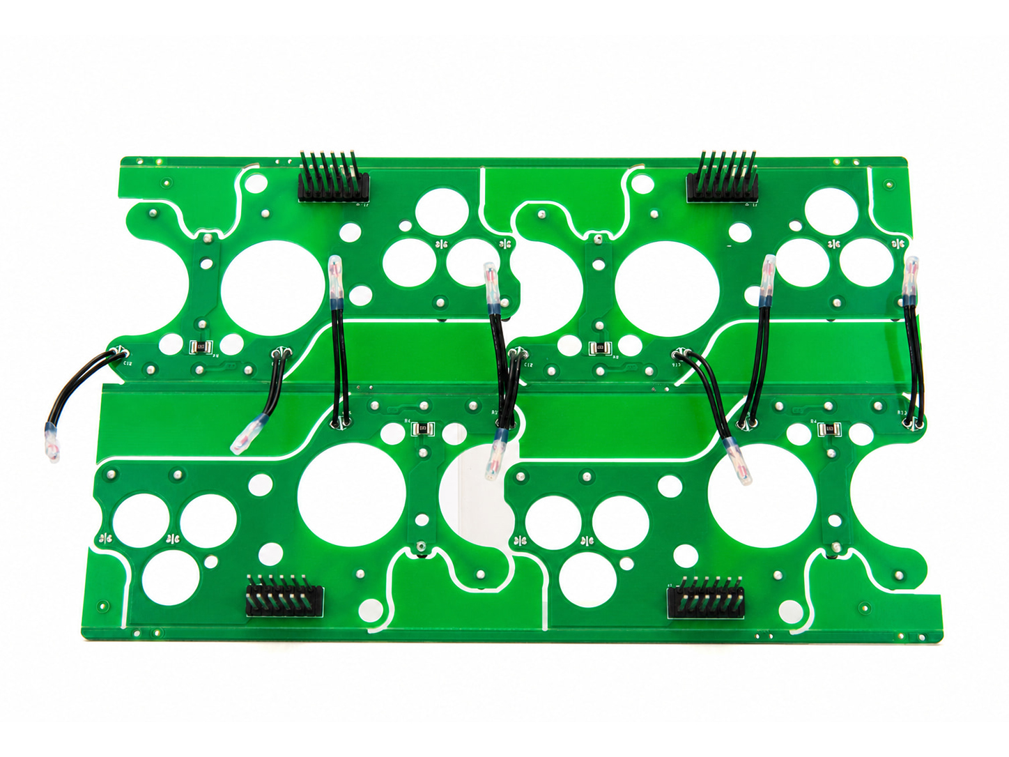 THT/DIP Assembly - Solder-Side View
Engineering Approach
For through-hole assemblies, mechanical reliability critically depends on precise thermal profiling and stable solder contact. At Sunhope, we deliver verifiable structural integrity across automated wave soldering, selective wave, and precision hand soldering processes. Our lines are tightly controlled to handle diverse component geometries — including axial/radial passives, multi-pin DIP ICs, and heavy-duty connectors — with process compliance for both lead-free RoHS and leaded specifications. To ensure these reliability parameters are fully realized, all assemblies undergo strict quality gating.
For an in-depth look at our verification workflows, please explore [The Section: Quality Testing & Inspection]

Filling the entire Plated Through-Hole (PTH) barrel creates a 3D metallurgical joint. This delivers significantly higher resistance to pull-out forces and mechanical shear than surface-mount pads.

Physically penetrating the board establishes high-mass electrical pathways, allowing components to easily handle the thermal loads and high-current transients typical of power electronics and transformers.

Deep barrel penetration distributes mechanical stress along the board’s vertical axis, making THT essential for industrial and field-deployed equipment exposed to continuous vibration.

Through-hole connections isolate mating stresses away from vulnerable copper traces, ensuring multi-pin headers, terminal blocks, switches, and relays remain structurally secure.
Strategic Alignment:At Sunhope, we believe a truly competitive through-hole assembly service isn’t about claiming to do everything, but about doing what we specialize in with uncompromising, transparent precision. We have purposefully structured our manufacturing capabilities, engineering team, and supply chain to directly support hardware innovators who value predictability over empty promises.
Through-hole projects are rarely isolated; your design likely integrates high-density SMT devices with THT connectors, transformers, or legacy ICs. Our production infrastructure is purpose-built for SMT+THT mixed-technology assembly, routing your boards seamlessly from high-precision reflow lines to automated wave or selective THT soldering under a unified manufacturing order—significantly reducing the logistical risk and overhead of coordinating fragmented vendors.
Component integrity is fundamental to field reliability. SUNHOPE sources THT/DIP materials to the approved BOM, prioritizing authorized distribution and using only customer-approved qualified channels under the agreed plan. For connector-, transformer- and power-device-heavy builds, we cross-check long-lead and obsolete parts early, review available manufacturer and lot information before release, and present supply options before scarcity becomes a production problem.
Disciplined turnkey assembly applies to your initial engineering trial just as it does to mass production. At Sunhope, prototypes undergo the exact same process controls used in volume manufacturing—including wave soldering thermal profiling, post-solder AOI validation, and selective soldering precision alignments. This early-stage engineering verification helps ensure your layout scales smoothly into volume manufacturing without unexpected insertion or wetting defects.
Trust begins with clarity. Our quotes are built from clear, itemized cost components, separating PCB fabrication, component sourcing, and assembly services. We ensure all standard quotation factors are fully detailed upfront, allowing purchasing managers to review costs with full visibility and financial confidence.
We strictly honor the rigorous intellectual and technical effort behind your hardware. Every component received or sourced is verified meticulously against the exact part numbers and manufacturers specified in your BOM. Sunhope strictly adheres to a zero-unauthorized-substitution policy; we will never alter a brand or substitute a component without your explicit, written engineering approval.
From quick-turn engineering prototypes to scheduled production runs, our lead time options are tailored to match the practical requirements of your project. We evaluate line capacity and component availability upfront based on actual floor data, confirming schedules that are genuinely achievable to protect your market timeline.
Different through-hole components are best served by different soldering methods. We map common component types to their recommended processes to establish clear baseline technical evaluation:
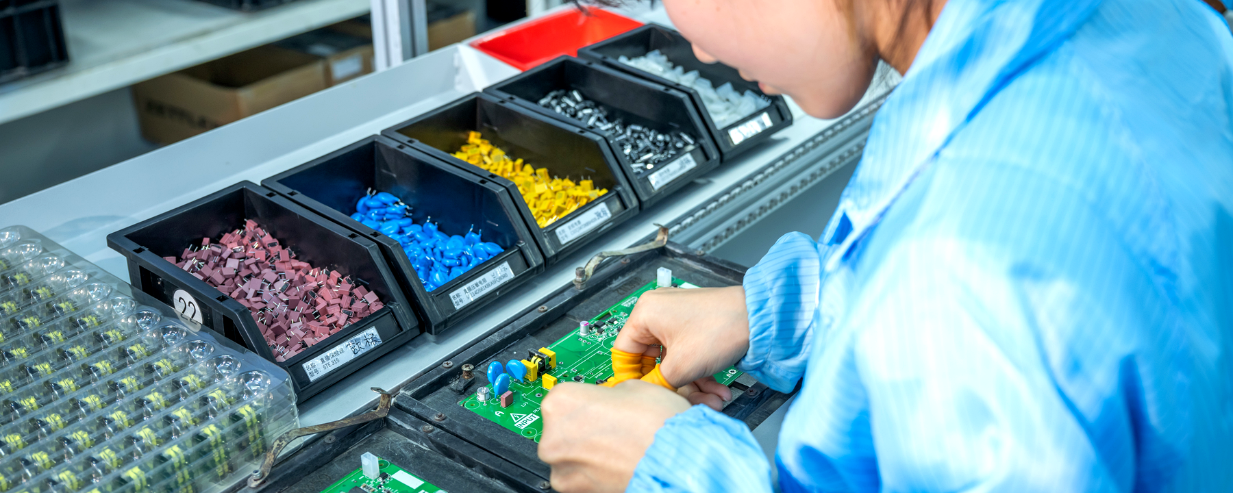
Capabilities & Process: Wave Soldering. Engineered to deliver high-throughput processing for standard radial/axial passives and simple connectors. This method is optimized for circuit boards with highly consistent, uniform through-hole layouts to achieve maximum manufacturing efficiency.
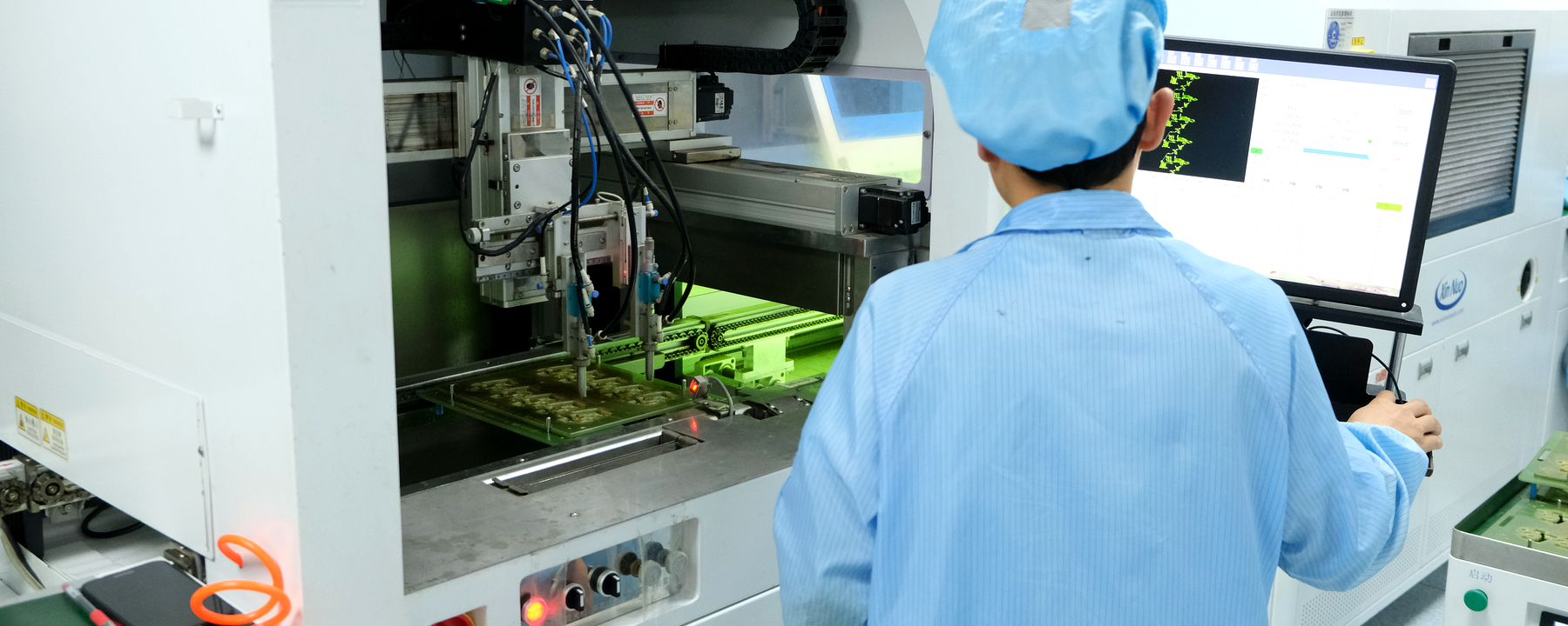
Capabilities & Process: Selective Wave Soldering. Calibrated specifically for mixed-technology boards featuring both SMT and THT components on the same side. This process applies precise, localized soldering to designated through-hole areas, effectively minimizing thermal disturbance to adjacent, pre-assembled SMT solder joints.
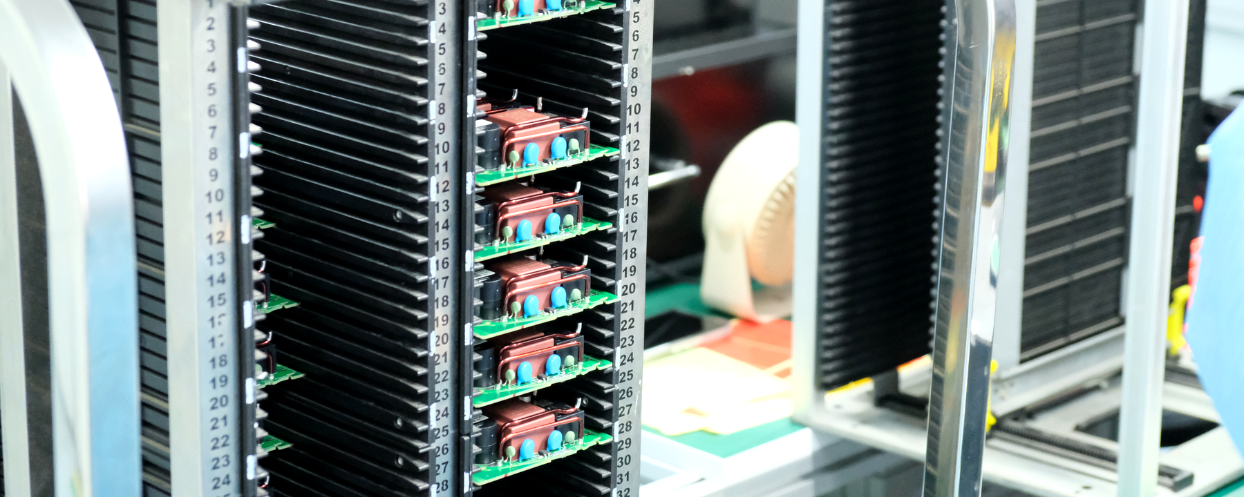
Capabilities & Process: Hand Soldering (or Selective Wave Soldering scaled for higher volumes). Designated for heavy-duty connectors, transformers, and large power components. This approach ensures precise localized heat control, protecting delicate internal structures or bulky, high-thermal-mass packages from catastrophic thermal stress.
Whether you are validating an initial engineering concept or scaling a market-ready product, our lines adapt dynamically to your batch requirements:
To continuously reduce manufacturing risks and accelerate your quoting speed, Sunhope provides this collaborative alignment guide. Adhering to these industry-standard DFM metrics helps ensure that your rigid board designs slide seamlessly into automated assembly with minimal administrative overhead.

We recommend maintaining optimized tolerances between the nominal component lead dimensions and drilled holes.
Undersized holes restrict automated/manual insertion and risk barrel copper damage, while excessive clearances can significantly weaken capillary wetting action.
Please orient and space tall components layout-wise relative to the soldering flow direction.
This layout discipline avoids wave solder shadowing effects during the wave soldering process and ensures reliable inspection access later.
Avoid direct, solid metal connections between THT pads and large internal/external copper planes.
Implementing proper thermal relief geometry prevents localized heat-sinking, which causes insufficient vertical fill and cold solder joints.
Maintain adequate layout clearance between through-holes and neighboring traces, ensuring a reliable soldermask dam.
This layout discipline avoids solder bridging defects during wave soldering.
To secure a fast and accurate quotation, please ensure your design package contains the following fully defined items:
Your BOM should detail the exact Manufacturer Part Number (MPN), package footprint, specified brand, and explicitly defined alternative/substitute criteria for every single line item. Incomplete BOM data is one of the most common causes of pricing turnaround delays.
Ensure that the component rotation and orientation values defined within your assembly drawing accurately match your layout data. Pre-aligning these orientation metrics significantly reduces upfront component placement offset risks.
Please notify us upfront if your specific design requires custom selective wave soldering pallets, and specify which keep-out zones apply. This ensures specialized tooling costs are integrated into the initial quote dynamically.
Sunhope has the capability to execute structured functional test (FCT) protocols. If FCT is required, you’ll need to provide the physical test fixtures, necessary firmware/programming tools, and detailed step-by-step test procedures. Please note that custom test methodology development is outside our standard scope.
High-reliability through-hole configurations shouldn't inherit high defect rates. At Sunhope, we don't just run production; we actively isolate and mitigate known THT failure modes through pre-calculated wave parameters and strict physical validation.
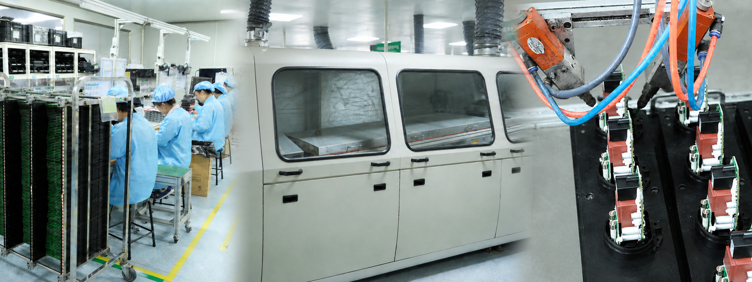
The Technical Challenge : Dense through-hole pin headers are highly prone to solder bridging during the wave soldering process due to localized solder accumulation and insufficient solder separation between adjacent leads.
The Sunhope Approach : Wave soldering parameters—including conveyor speed, laminar wave height, and flux application volume—are carefully tuned per board layout. We deploy post-solder inline AOI and visual inspection, where included in the approved inspection plan, to intercept and isolate micro-bridging before boards move downstream.
The Technical Challenge : Mixed SMT+THT layouts risk remelting, component displacement, or structurally weakening pre-soldered underside SMT joints under the extreme thermal conditions of the molten solder wave.
The Sunhope Approach : We utilize highly targeted selective wave soldering or custom-engineered synthetic stone wave soldering pallets to physically shield pre-soldered underside SMT components, ensuring liquid tin contact is restricted exclusively to designated through-hole lead target zones without disturbing surrounding SMT areas.
The Technical Challenge : Heavy connectors and high-mass power components are prone to severe structural lead stress, insufficient vertical barrel fill, or cold joints if their high thermal inertia prevents them from reaching proper wetting temperatures evenly.
The Sunhope Approach : Specialized manual post-soldering stations feature micro-processor controlled tip temperatures and strictly audited dwell times to support reliable intermetallic layer formation for heat-sensitive or bulky components. Heavy-duty joints are subject to rigorous visual inspection, with Functional Testing (FCT) conducted per project requirements where applicable.
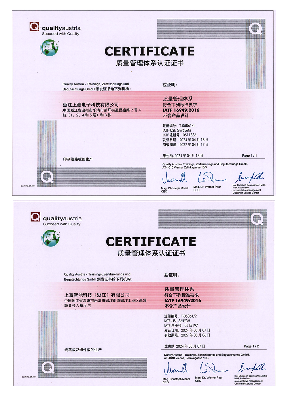
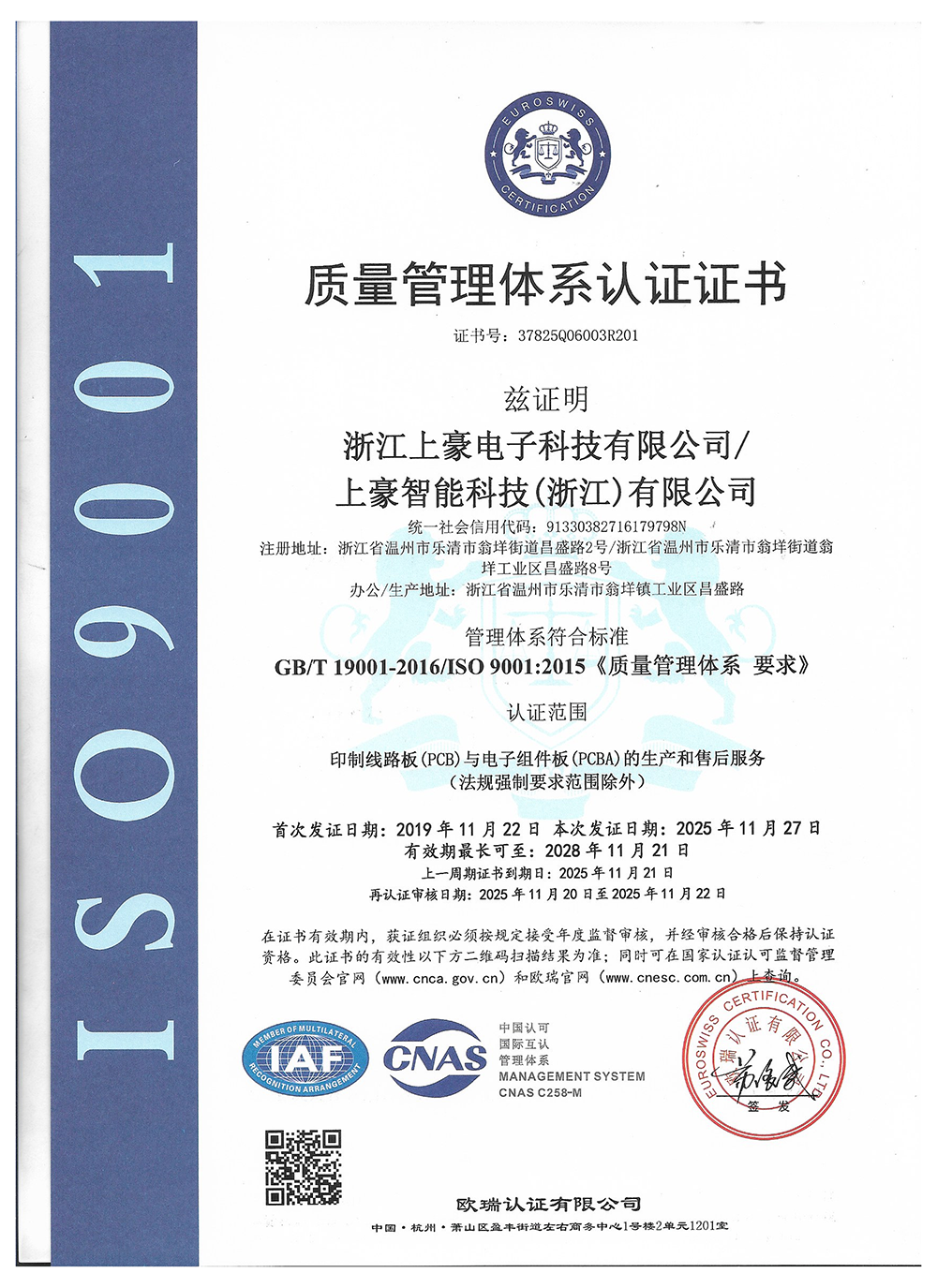
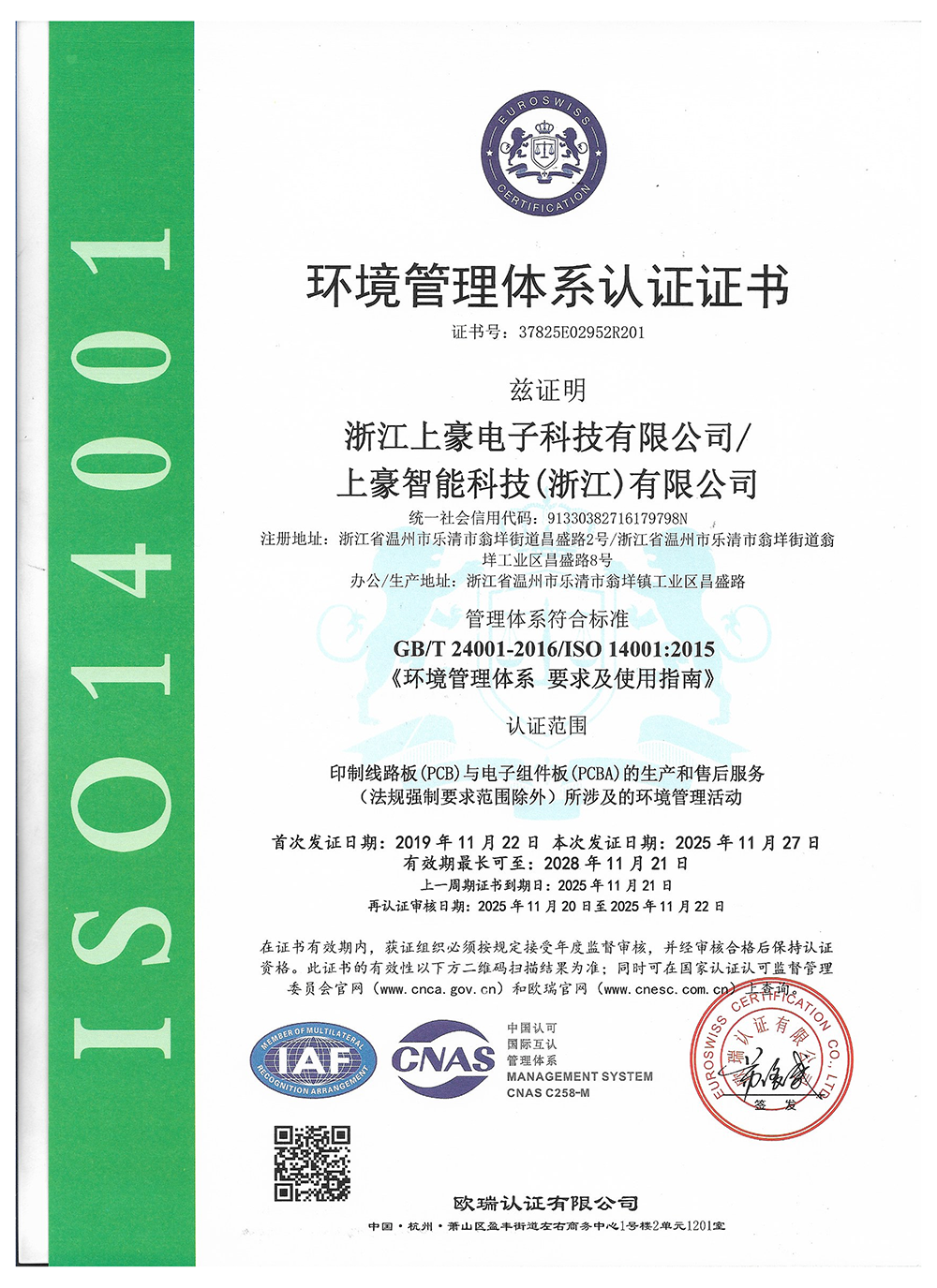
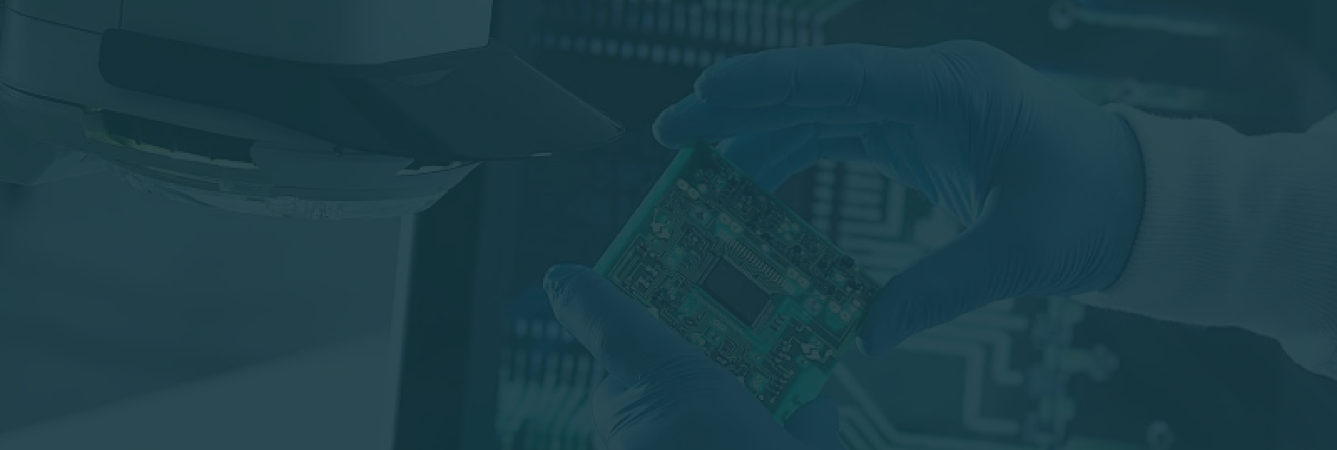
Our sourcing capability spans a broad range of Through-Hole assembly requirements — from standard passive components to heavy-duty power devices and precision connectors:
Standard passive components: resistors, capacitors, electrolytic capacitors, inductors, crystal oscillators
Through-hole semiconductor devices: DIP ICs, microcontrollers (MCU), optocouplers, logic ICs
Connectors & headers: multi-pin connectors, shrouded headers, terminal blocks, board-to-board connectors
Power & electromechanical components: transformers, relays, power inductors, high-current fuses, switches
Our components are sourced through authorized, audited global distributors or verified domestic official channels. Spot market and grey-channel supply are not part of our sourcing practice — our commitment to authorized channels holds regardless of schedule pressure or component availability constraints.
Components are cross-verified against your exact Manufacturer Part Number (MPN), date code, and approved manufacturer before entering our production floor. Sunhope adheres to a zero-unauthorized-substitution policy: no brand change, equivalent swap, or component substitution is made without your explicit written engineering approval.
For critical silicon and long-lead components, our engineering team pre-screens End-of-Life (EOL) status and allocation risk before your order is confirmed — not after production has already started. This early intervention protects your timeline from supply disruptions that are often only discovered after production has already begun.
Having these technical documents ready when you submit your RFQ allows our engineering and sourcing teams to return an accurate quote in less time, reducing unnecessary back-and-forth communication.
Through-Hole (DIP) assembly relies heavily on the structural and thermal reliability of the bare PCB during the wave soldering process. Because Sunhope fabricates the bare PCB internally, this supports reliable thermal alignment and precise hole-to-pad registration between board manufacturing and component insertion.
Note: See each board type’s dedicated detail page below for fabrication-side technical specifications
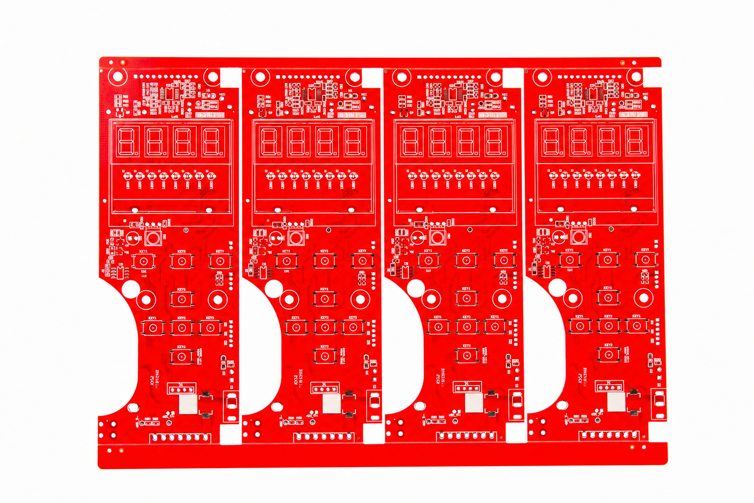
A reliable and cost-effective foundation for classic through-hole applications, such as power supply modules, home appliances, and fundamental consumer electronics circuits.
Explore Single/Double-Sided Capabilities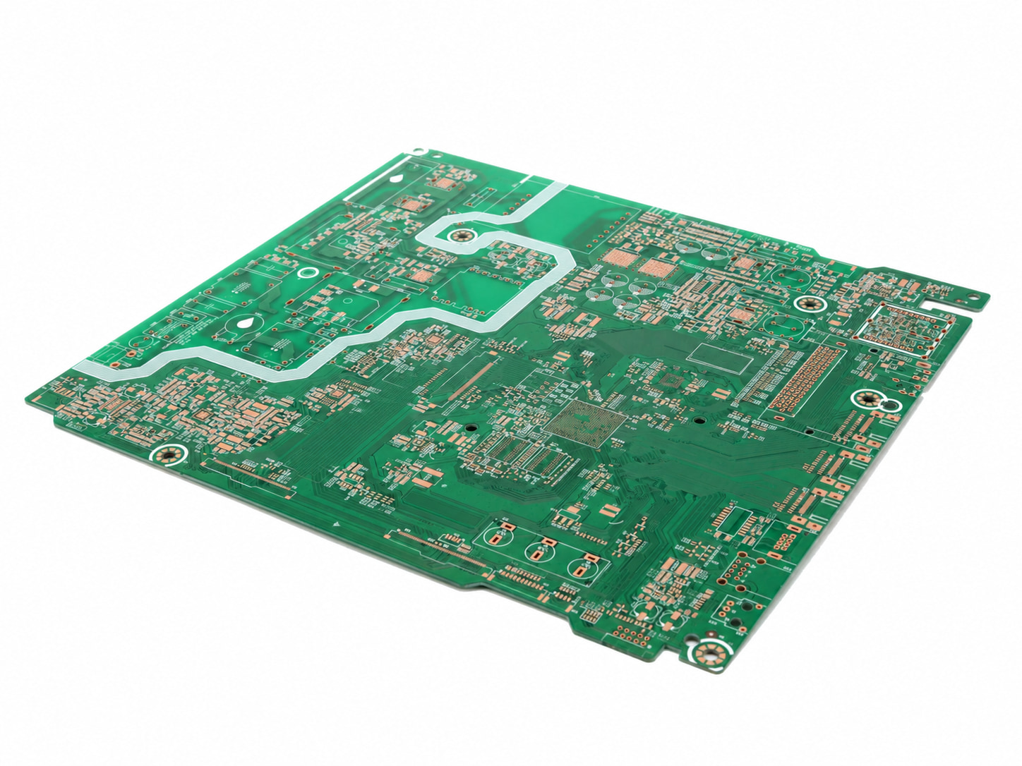
Engineered for complex industrial control and power routing requirements within our 1-8 layer fabrication scope, supporting stable internal power and ground planes.
Explore Multilayer Fabrication Specs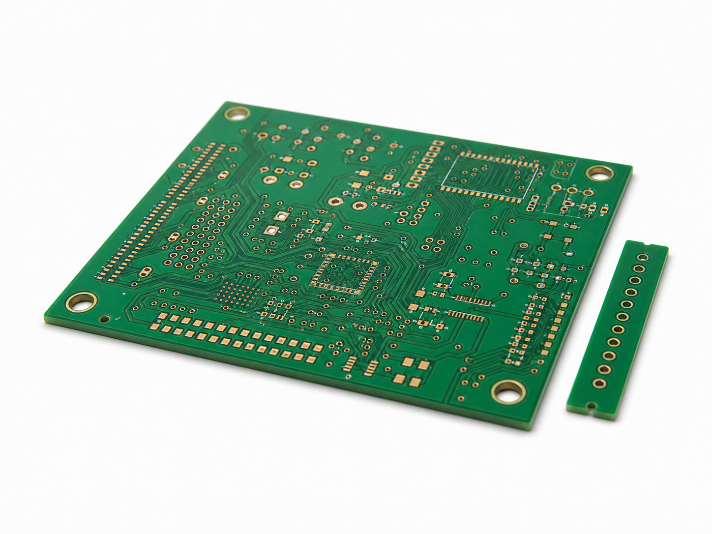
Highly recommended for multilayer through-hole assemblies to withstand severe, repeated thermal shock during wave soldering, significantly reducing the risk of board delamination.
Explore High-TG Material Options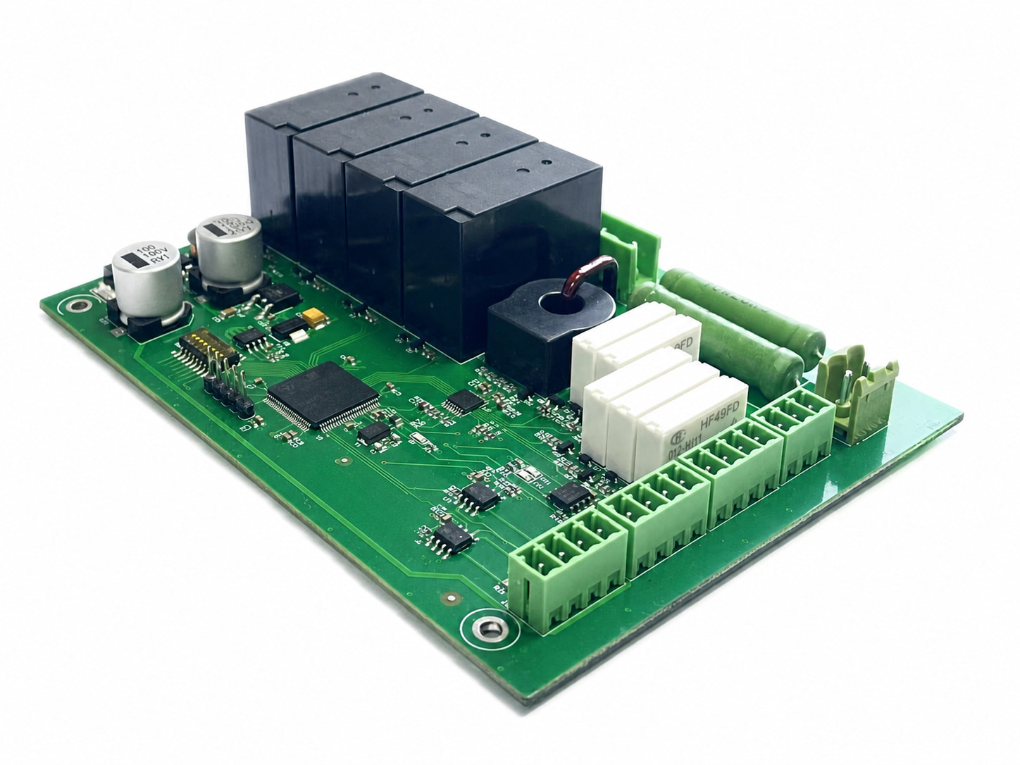
Many through-hole (THT) designs require high-density SMT components (fine-pitch ICs, passives, or BGAs) on the same board. Sunhope handles this entire mixed-technology workflow in-house—allowing you to consolidate your order with a single vendor.
Explore Surface Mount (SMT) Assembly ServicesWe specialize in the production and assembly of 1-8 layer circuit boards. Our engineering team works to maintain stable thermal control and precise hole-to-pad registration across all 1-8 layer configurations during the wave soldering process.
Yes. We offer flexible commercial supply modes, cooperating with either full turnkey sourcing through our authorized sourcing channels, or pure consigned assembly using components supplied directly by the customer.
Yes. For mixed-technology boards, we design and manufacture custom wave soldering pallets (synthetic stone fixtures) to shield pre-soldered underside SMT components while allowing full wave contact for through-hole pins.
We enforce a strict First Article Inspection (FAI) protocol immediately after the first board completes wave soldering. Production lines use visual alignment guides, and QC inspectors cross-check polarity against your assembly drawings before mass release.
We execute standard visual inspection and post-wave AOI per the approved inspection plan. For functional testing (FCT), we can execute your specified test protocol when you supply the physical test fixtures, test procedures, and necessary firmware. For in-circuit testing (ICT), flying-probe testing is available without requiring a customer-supplied dedicated fixture. Test feasibility and coverage are confirmed from the applicable CAD/netlist, BOM, component and test-requirement data. Bed-of-nails ICT is also available upon request and requires a dedicated fixture and approved test program.
We maintain a highly flexible production stance to support our customers. We welcome small-batch engineering prototypes for layout verification as well as continuous multi-layer mass production runs, offering tailored setup options for each.
Double-sided THT designs require a structured, multi-stage process. Typically, primary-side components are processed via automated wave soldering with a custom fixture, while secondary-side or protruding leads are secured using selective soldering or precision manual post-soldering.
Yes. Our engineering team reviews your Gerber and assembly data upfront to verify hole-to-pad ratios, annular ring sufficiency, and solder mask clearances, minimizing potential wave-soldering bridges or thermal sinking issues.