Phase 1
Pre-Production & Engineering
- 01 BOM Review
- 02 DFM / DFA Review
- 03 PCB Fabrication
- 04 Stencil Fabrication
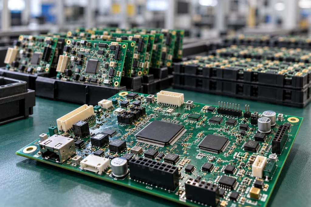
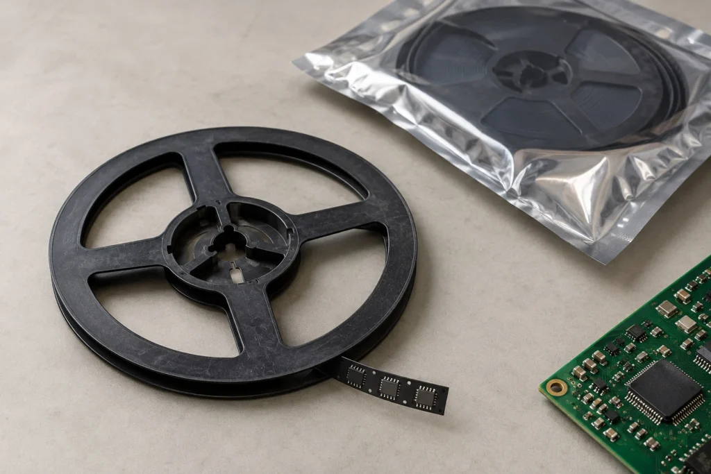
Surface Mount Technology (SMT) assembly serves as the backbone of modern electronics manufacturing. This automated process mounts electronic components—including chips, resistors, capacitors, connectors, and more—directly onto designated pads on the circuit board surface using precisely applied solder paste, then bonds them securely within a controlled reflow oven. Unlike traditional through-hole assembly, SMT removes the need to drill holes for component leads. By utilizing this surface-level placement and reflow-soldering technology, it allows for significantly higher component density, smaller product form factors, and the reliable, fine-pitch designs required to power today’s complex connected devices.
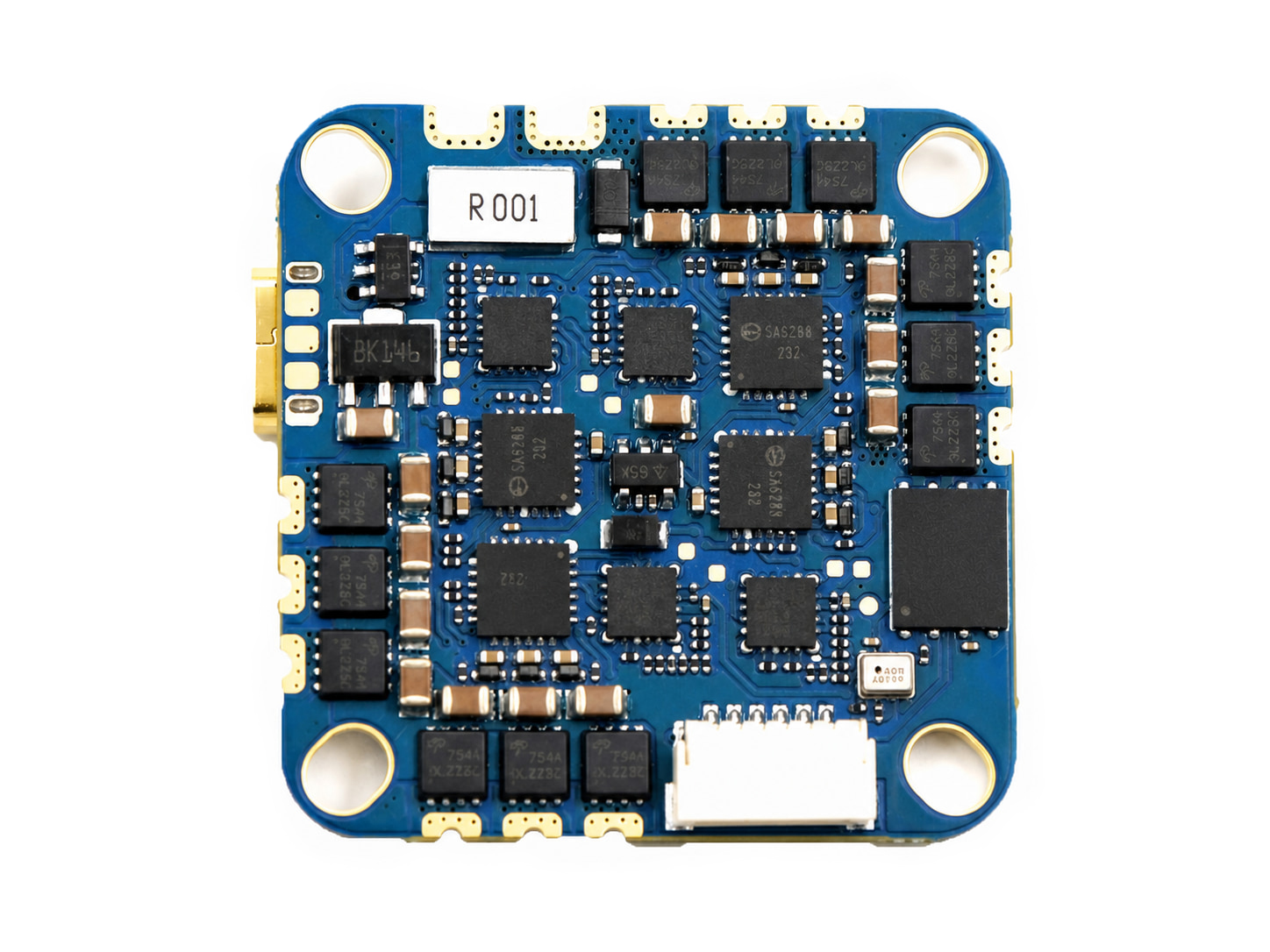 Compact SMT Assembly
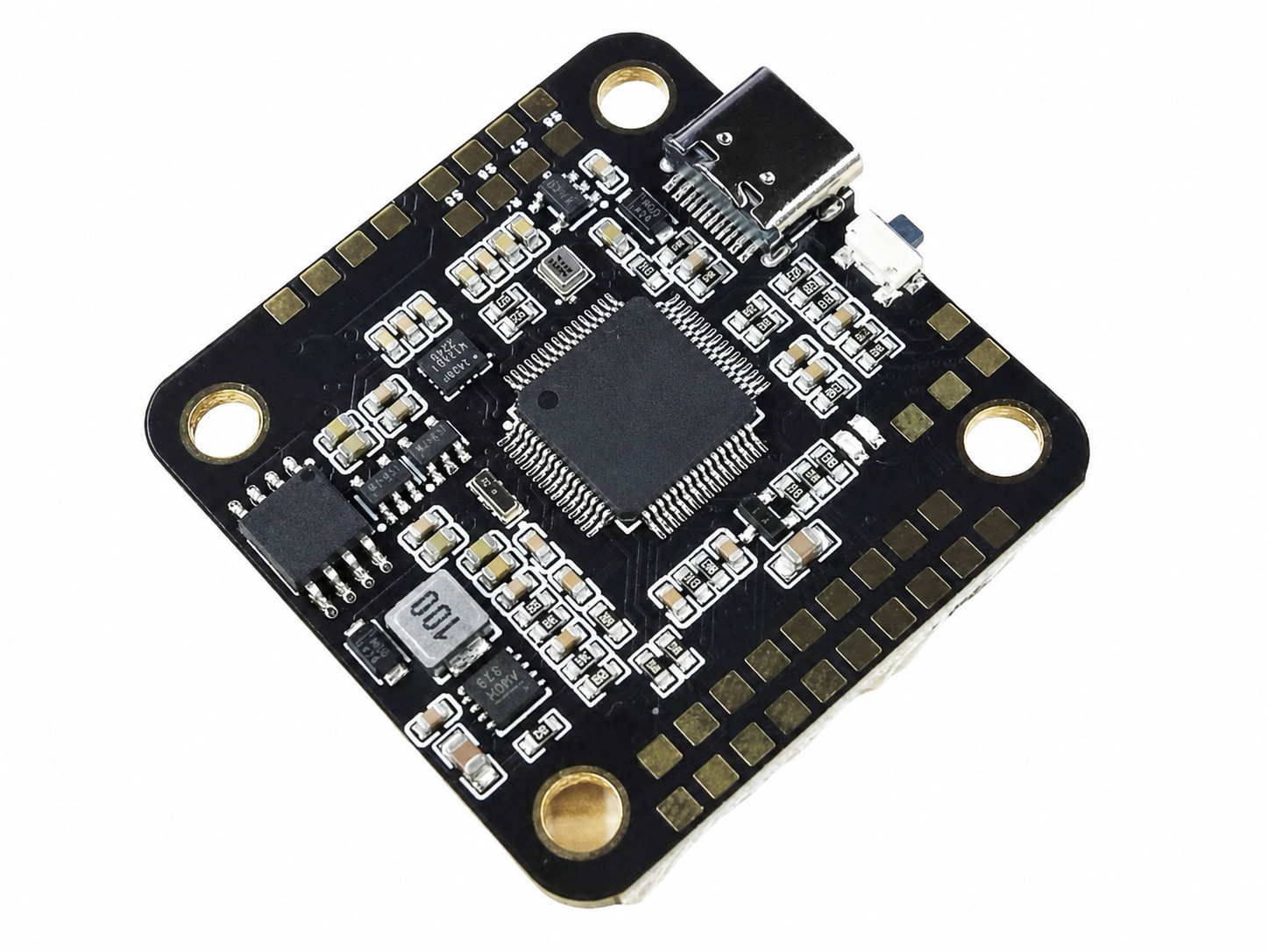 QFP-Based SMT Assembly
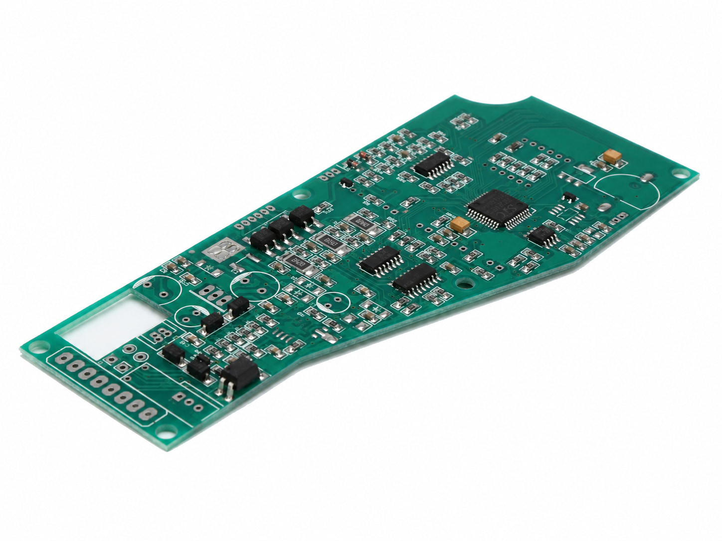 Long-Format SMT Assembly
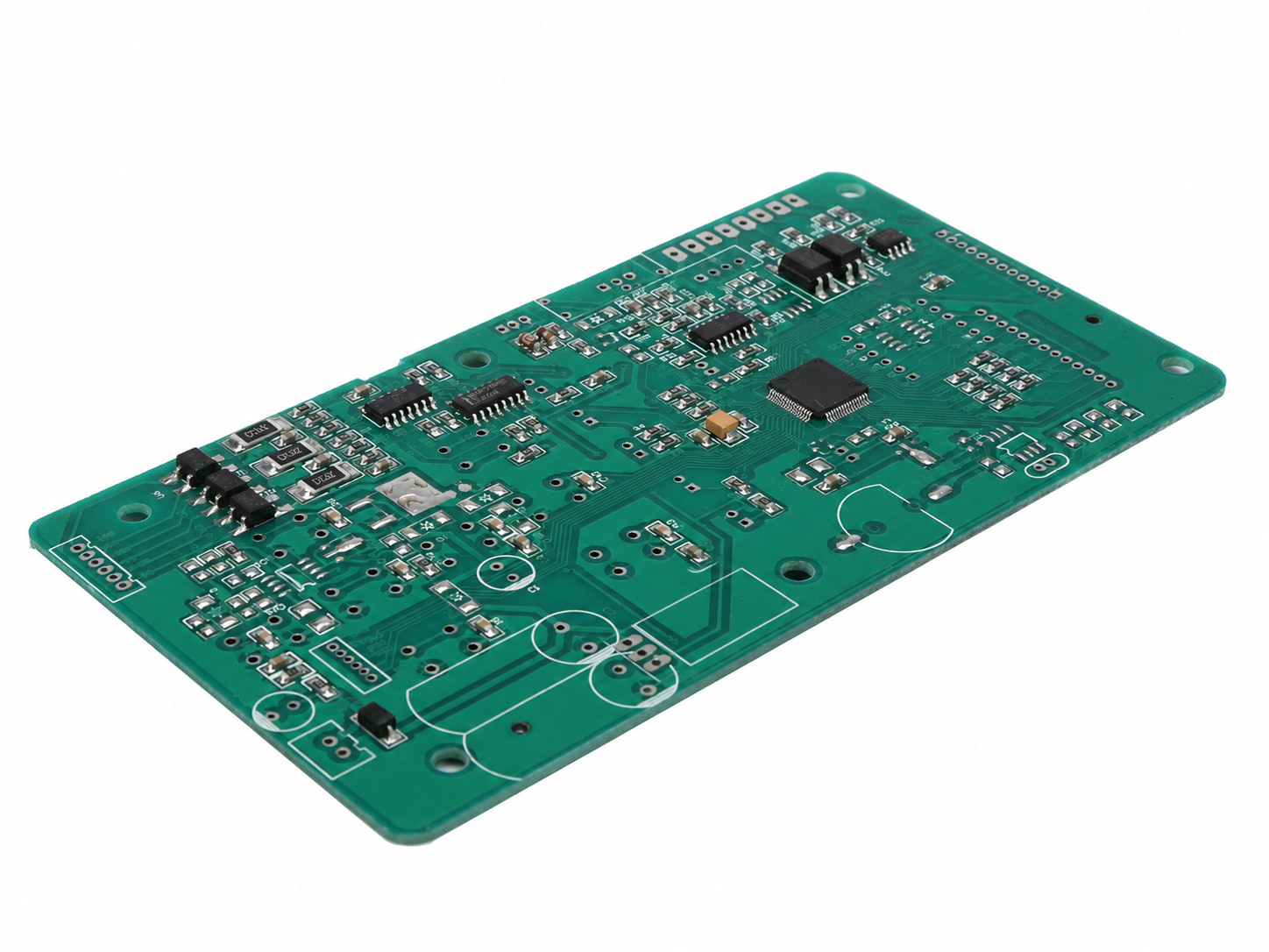 Multi-IC SMT Assembly
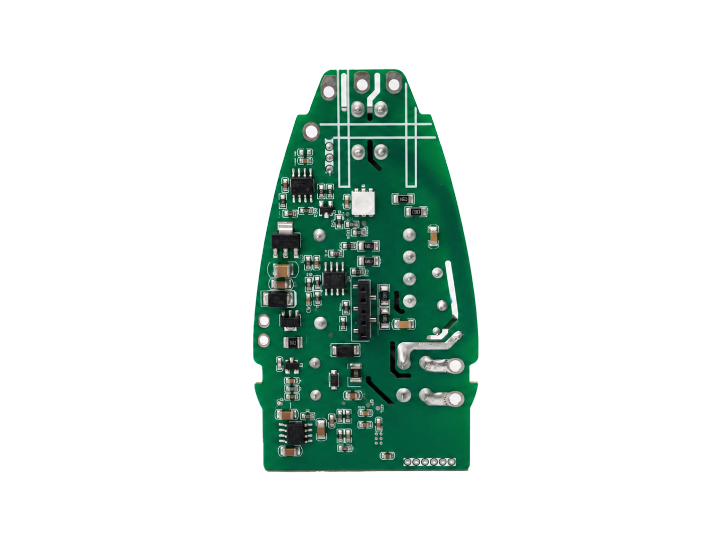 Irregular-Shape SMT Assembly
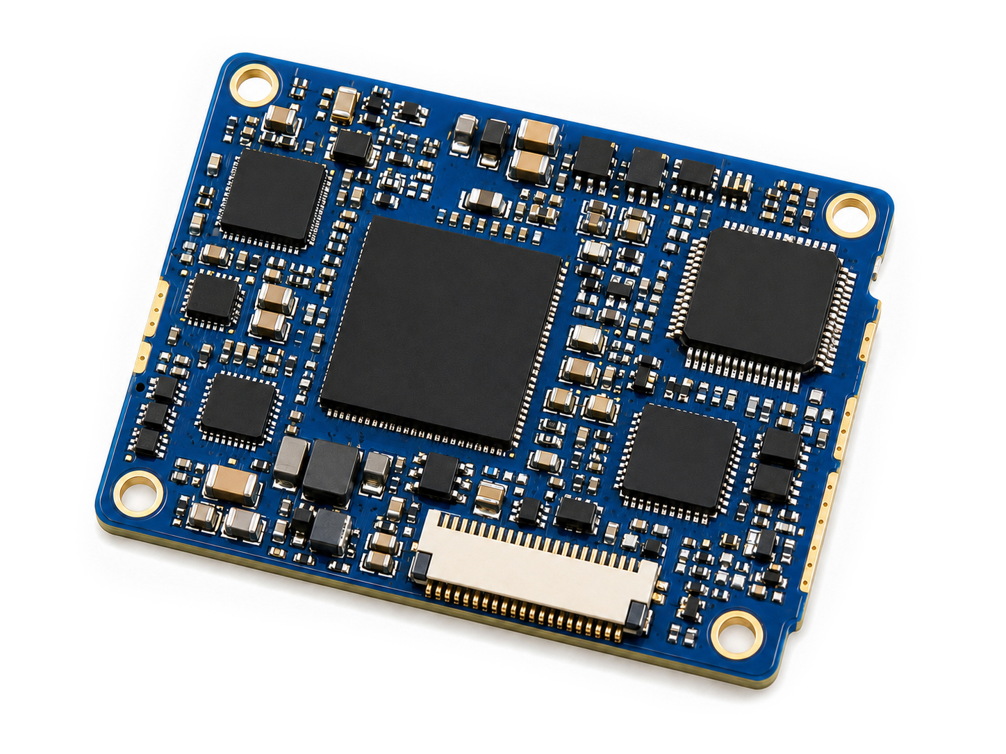 High-Density SMT Assembly
Engineering Approach
As electronic designs trend toward higher density and smaller footprints, placement accuracy becomes one of the deciding factor for PCBA reliability. At Sunhope, we don’t just state theoretical equipment limits; we deliver stable, verifiable precision in daily production. Our SMT lines are tightly controlled to handle advanced fine-pitch components and micro-miniature packages, ensuring your designs are replicated consistently to engineering specifications. To ensure these precision parameters are fully realized in production, all fine-pitch assemblies undergo automated, closed-loop verification.
For an in-depth look at our complete testing workflows and equipment, please explore [The Section: Quality Testing & Inspection].

Components are mounted on both sides of the board without the need for drilled holes, fitting far more functionality into the same footprint.

Ideal for compact, portable, and wearable electronic products where internal enclosure space is at a premium.

Automated pick-and-place precision combined with conveyorized reflow scales smoothly from engineering prototypes to mass production with repeatable results.

Shorter lead lengths significantly reduce parasitic inductance and capacitance, supporting the high-speed and RF designs.
At Sunhope, we believe a truly competitive SMT service isn’t about claiming to do everything, but about doing what we specialize in with consistent, transparent precision. We have purposefully structured our manufacturing capabilities, engineering team, and supply chain to directly support hardware innovators who value predictability over empty promises.
We maintain strict process parameter controls regardless of your order size. Whether running a minimal engineering trial or an extended production batch, our thermal reflow profiles, placement speed and process parameters, and automated inspection criteria remain strictly aligned to protect the structural and electrical performance of your design.
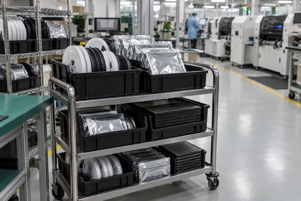
Component integrity is critical to product survival. Our dedicated sourcing team utilizes a trusted network of authorized global distributors to enforce strict anti-counterfeit mitigation. We prioritize genuine, original components with supply chain traceability available upon project requirement, cross-referencing part numbers early to identify hard-to-find or obsolete parts before they impact your timeline.
Reliable turnkey assembly isn’t reserved exclusively for high-volume orders; it is available starting from your very first prototype stage. Crucially, when we assemble your engineering prototypes, we apply the same disciplined process controls and automated 3D SPI/AOI validation used in mass production. This early engineering alignment helps your design scale smoothly into production, reducing the risk of unexpected defects.
Trust begins with clarity. SUNHOPE’s itemized quotations show the work the project actually needs—assembly, component sourcing, PCB fabrication when selected, tooling, testing and other agreed items—so purchasing and engineering teams can see cost ownership, exclusions and change impact before release. Customers gain the flexibility to select only the scope that adds value to their program.
We strictly honor the rigorous intellectual and technical effort behind your hardware. Every component received or sourced is verified meticulously against the specified part numbers and manufacturers in your BOM. Sunhope strictly adheres to a zero-unauthorized-substitution policy; we will never alter a brand or substitute a component without your explicit, written engineering approval.
From quick-turn engineering prototypes to scheduled production runs, our lead time options are tailored to match the practical requirements of your project. We evaluate line capacity and component availability upfront based on actual floor data, confirming schedules that are genuinely achievable to protect your market timeline.
We group our placement capabilities into three distinct technical tiers to match your design's integration density, allowing for clear baseline quoting and specialized processing where required:
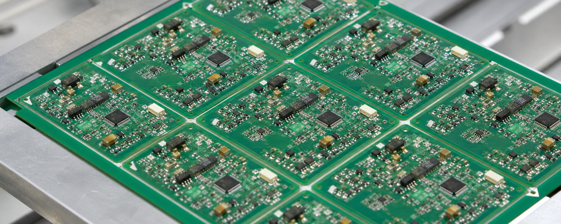
Capabilities: High-efficiency, standard-rate placement of passive components (including resistors and capacitors down to 0603 and 0402), common diodes, transistor packages (SOT), and surface-mount (SMT) connectors.
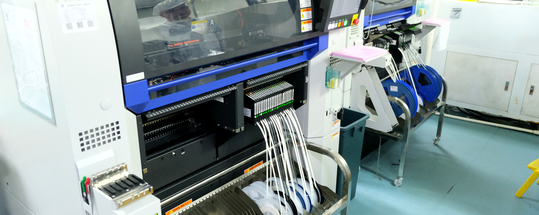
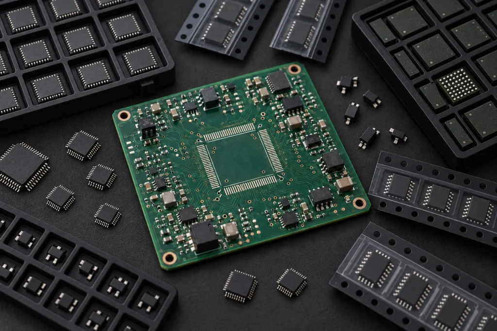
Capabilities: Reliable alignment and mounting for complex integrated circuits including BGA, SOP, QFP, and QFN down to a 0.3mm pitch. Fully verified for BGA packages with a ball pitch ≥ 0.3mm and a minimum ball diameter of 0.15mm. CSP and Micro-BGA packages are supported subject to project engineering review.
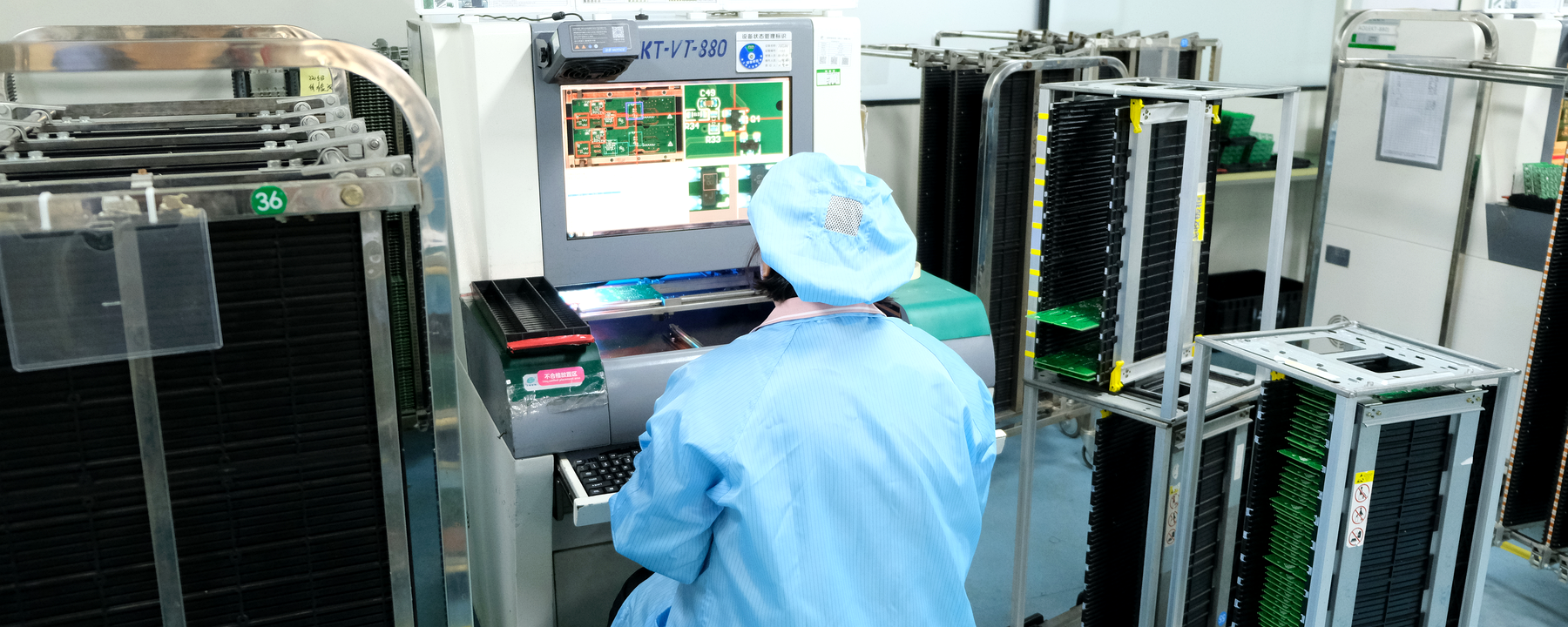
Capabilities: Advanced process controls calibrated for ultra-dense layouts, supporting micro-footprint components down to 008004 (Imperial) / 0201 (Metric) miniature chip packages (subject to prior engineering evaluation and specialized setup).
Whether you are validating an initial engineering concept or scaling a market-ready product, our lines adapt dynamically to your batch requirements:
To continuously eliminate manufacturing risks and accelerate your quoting speed, Sunhope provides this collaborative alignment guide. Adhering to these industry-standard DFM metrics helps ensure that your rigid board designs slide seamlessly into automated assembly with minimal administrative delays.

We strictly recommend following IPC-7351 land pattern guidelines.
Undersized or asymmetrical pads are verified as the leading cause of tombstoning defects on small passive chip components (such as 008004 and 0201 packages).
Please place global and local fiducial marks per standard layout design.
This supports our high-precision optical placement vision systems in precisely registering and aligning fine-pitch BGAs, QFNs, and advanced IC packages.
Maintain adequate layout clearance between fine-pitch parts and taller neighboring components.
This layout discipline avoids severe thermal shadowing effects during the reflow process and ensures reliable rework access later if needed.
Avoid direct, solid metal connections between SMD pads and large internal/external copper planes.
Implementing proper thermal relief geometry prevents localized heat-sinking, which causes insufficient reflow and tombstoning.
To secure a fast and accurate quotation, please ensure your design package contains the following clearly defined items:
Your BOM should detail the exact Manufacturer Part Number (MPN), package footprint, specified brand, and explicitly defined alternative/substitute criteria for every line item. Incomplete BOM data is the leading cause of pricing turnaround delays.
Ensure that the component rotation and orientation values defined within your Centroid/CPL file accurately match your Gerber layout data. Pre-aligning these orientation metrics significantly reduces upfront component placement offset risks.
Please notify us upfront if your specific design requires mandatory post-reflow X-Ray inspection, and specify which internal voiding standards (e.g., IPC class metrics) apply. This allows specialized inspection costs to be integrated into the initial quote.
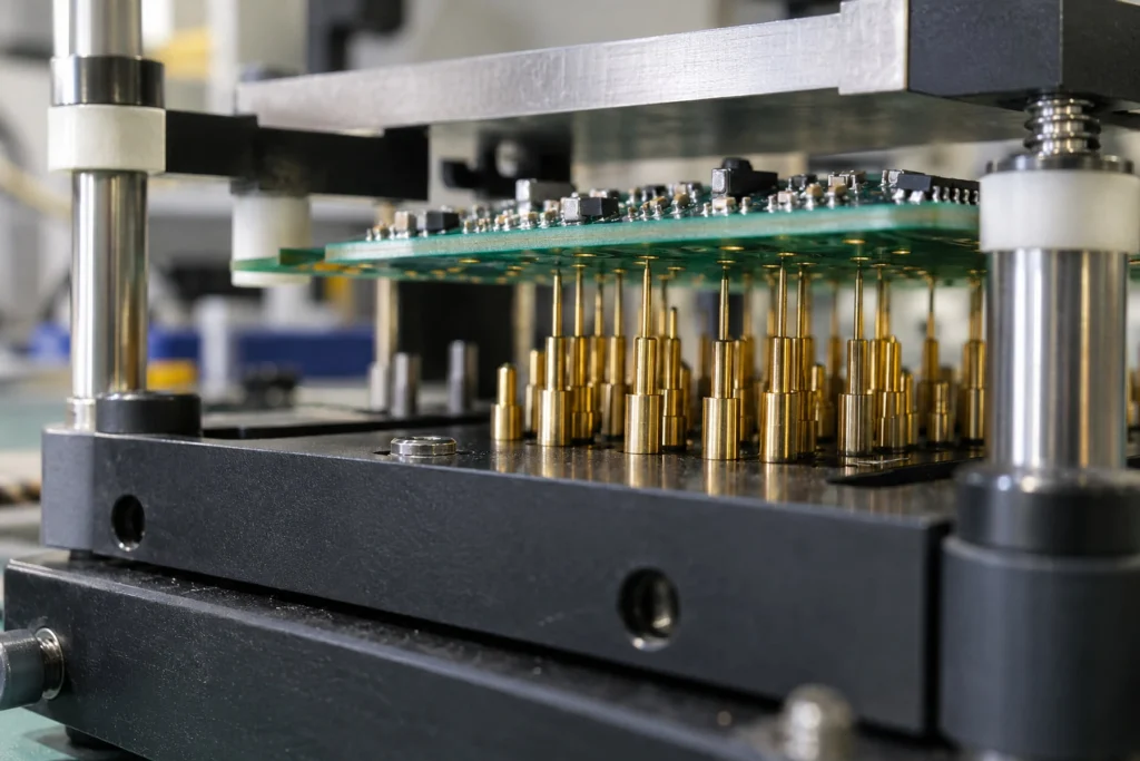
Sunhope is experienced in executing rigorous functional test (FCT) protocols. If FCT is required, you will need to provide the physical test fixtures, necessary firmware/programming tools, and detailed step-by-step test procedures. Please note that custom test methodology development is outside our standard scope.
High-precision, complex rigid designs shouldn't inherit high defect rates. At Sunhope, we don't just run production; we actively isolate and mitigate known SMT failure modes through pre-calculated parameters and strict physical validation.
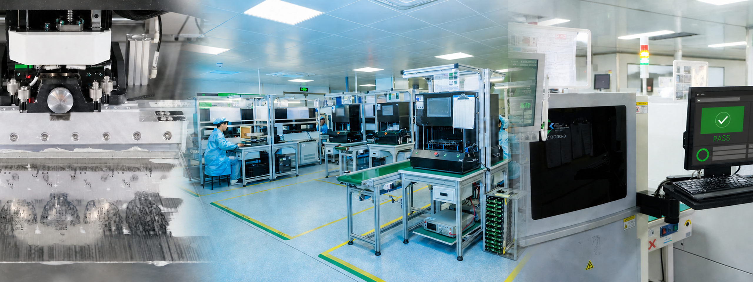
The Technical Challenge:Fine-pitch pads are highly sensitive to microscopic stencil and squeegee variations. A fraction of a millimeter of deviation can lead to insufficient solder or severe bridging before reflow even begins.
The Sunhope Approach: Stencil aperture geometry and automatic print parameters are dynamically calibrated per individual pad pitch. For approved projects, we deploy 100% inline 3D SPI to measure deposit volume, height, and alignment—automatically intercepting affected prints before component placement so they can be corrected or reprinted as required.
The Technical Challenge:Solder joints are completely hidden beneath BGA/QFN packages. Critical defects like internal micro-voiding and subtle bridging are entirely invisible to automated optical or manual visual inspection.
The Sunhope Approach: We address tracking blind spots by utilizing full 3D X-Ray inspection paired with automated voiding analysis. Where X-Ray inspection is specified, every hidden array joint is non-destructively verified against rigorous industry density criteria before the batch proceeds to final packaging.
The Technical Challenge:Ultra-miniature passive chips (such as 008004 (Imperial) / 0201 (Metric) components) are highly prone to “tombstoning” (lifting off one pad) due to unbalanced surface tension caused by uneven reflow heating.
The Sunhope Approach: Reflow thermal profiles are customized and tuned to match the unique thermal mass of your board layout. Concurrently, machine placement accuracy is tightly restricted to ±0.035mm (with a process capability index CPK ≥ 1.0, under defined production conditions), ensuring both terminal pads wet symmetrically.

Our sourcing capability spans the full spectrum of SMT assembly requirements — from high-volume standard passives to advanced fine-pitch active devices:
Standard passive components: resistors, capacitors (MLCC), inductors, crystal oscillators
Active semiconductor devices: microcontrollers (MCU), logic ICs, power management ICs
Fine-pitch & advanced packages: BGA, QFN, QFP, CSP, SOP
Connectors & electromechanical: surface-mount (SMT) connectors, switches, sensors
Every sourcing route is documented against the approved material plan. Authorized distribution remains the preferred path; if availability requires another customer-approved qualified source, its origin, available traceability, commercial impact and risk are disclosed before material release. No substitute enters production without written customer authorization.
Every component received is cross-verified against your exact Manufacturer Part Number (MPN), date code, and approved manufacturer before it enters our production floor. Sunhope strictly adheres to a zero-unauthorized-substitution policy: we will never alter a brand, swap an equivalent, or substitute a component without your explicit written engineering approval.
For critical silicon and long-lead components, our engineering team pre-screens End-of-Life (EOL) status and allocation risk before your order is confirmed — not after production has already started. This early intervention protects your timeline from supply disruptions that can otherwise surface mid-production.
Having these technical documents ready when you submit your RFQ allows our engineering and sourcing teams to return an accurate quote in less time, reducing unnecessary back-and-forth communication.
Fine-pitch SMT assembly is most often paired with these specific PCB categories. Because Sunhope fabricates the bare boards internally, we are able to achieve tighter thermal and dimensional synchronization between board manufacturing and component placement.
(Note: See each board type’s dedicated detail page below for fabrication-side technical specifications)
(Note: See each board type's dedicated detail page below for fabrication-side technical specifications)
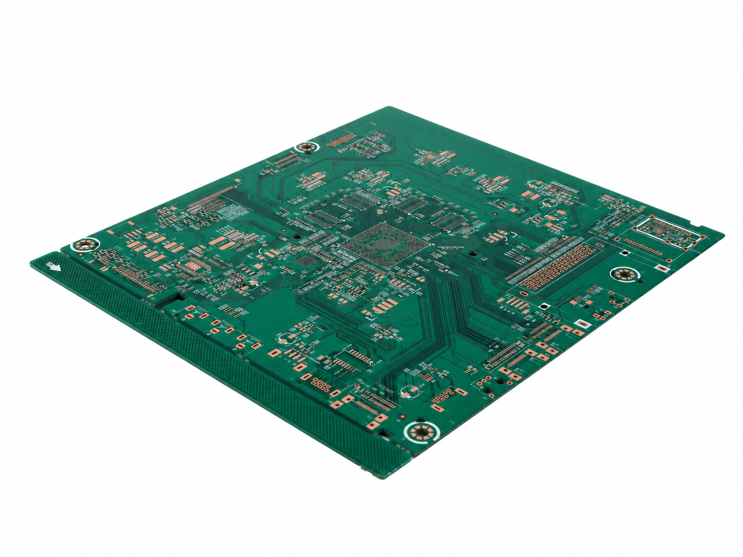
Optimized for dense BGA/QFN layout designs requiring dedicated, stable internal power and ground planes to suppress noise.
Explore Multilayer Fabrication Specs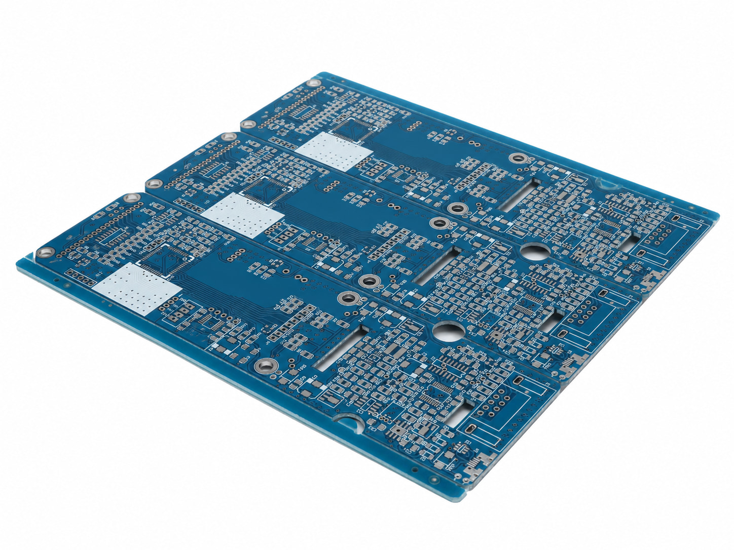
Engineered for high-speed differential pairs and controlled-impedance routing net works running directly beneath fine-pitch silicon packages.
Explore Impedance Control Matrix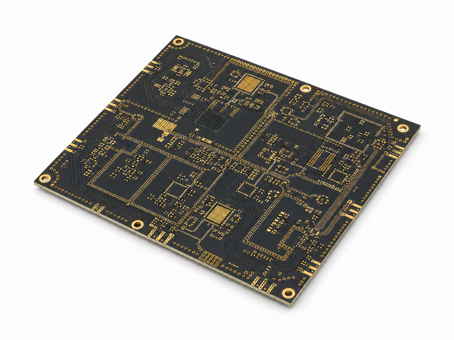
Tailored for complex RF front-end modules and wireless communication links utilizing highly sensitive, fine-pitch RF ICs.
Explore High-Frequency Material Options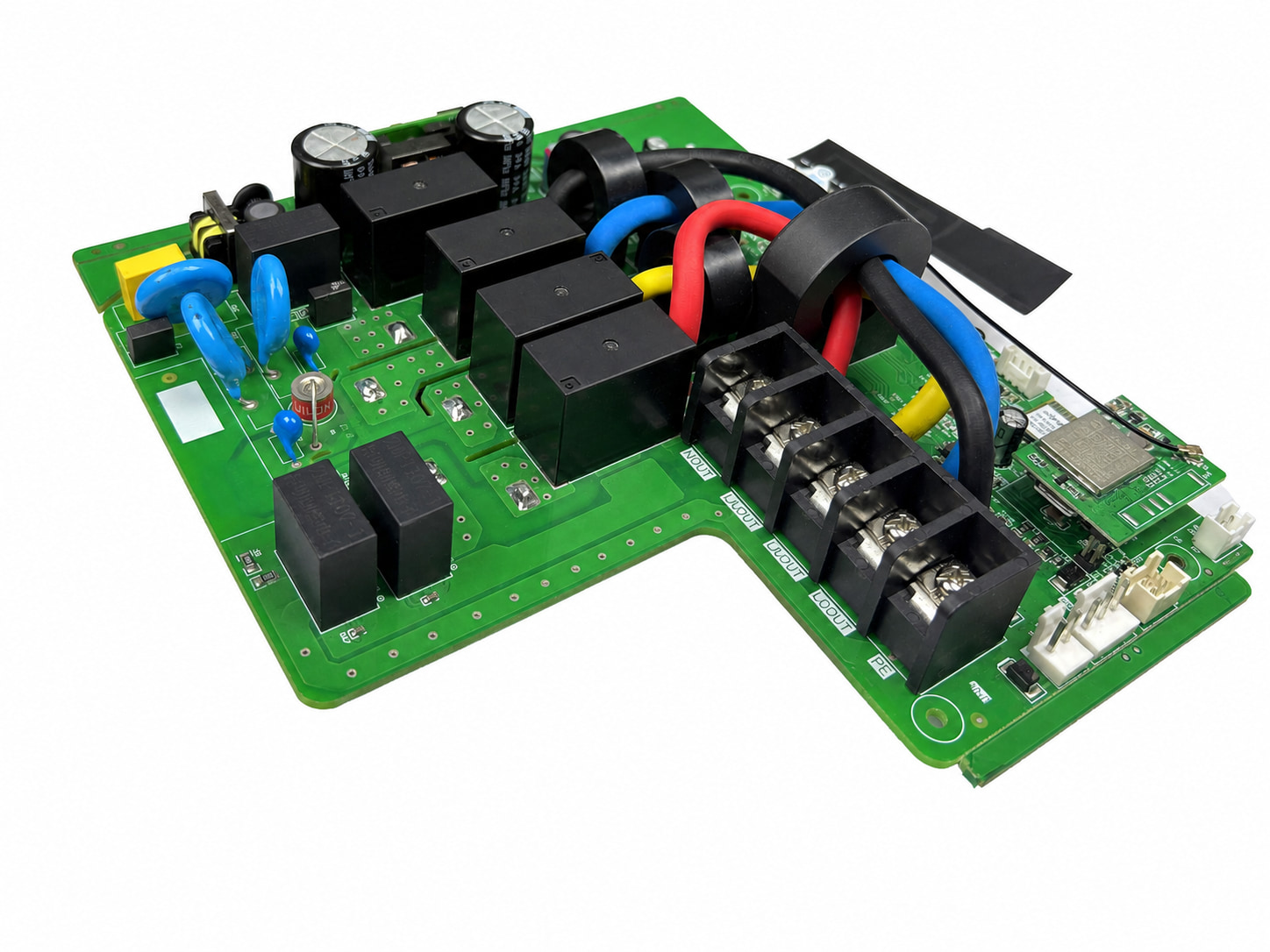
Many PCB designs combine SMT with through-hole components (connectors, power devices, or legacy ICs). Sunhope seamlessly handles this entire mixed-technology workflow in-house — eliminating the need to split your order across multiple vendors.
Explore Through-Hole (THT/DIP) Assembly ServicesOur high-precision automated modular placers are fully calibrated to handle ultra-miniature passive components down to 008004 (Imperial) / 0201 (Metric)footprints, as well as fine-pitch BGAs and QFNs. Mass production at this component scale requires DFM review prior to confirmation.
Yes,We offer flexible commercial supply modes, cooperating with full turnkey sourcing through our verified component network, partial turnkey arrangements where sourcing is split between Sunhope and the customer, or pure consigned assembly using components supplied directly by the customer.
Yes,We utilize fully automated SMT production lines for surface-mount devices, paired with flexible manual and semi-automated insertion lines backed by controlled wave soldering for through-hole (DIP) processing.
A detailed BOM with specific MPNs, packages, and designated brands prevents technical ambiguity. Incomplete component data is the leading cause of sourcing and quotation turnaround delays.
Before a full production run, we use our automated first-article inspection system to verify the initial assembly against the approved BOM, CPL/pick-and-place data and assembly references. When programming is included, we also confirm the correct device, firmware file and revision through the agreed programming and readback or functional-verification process. These two connected checks help us identify setup, component and programming discrepancies before they are repeated across the batch.
Yes, we highly encourage you to specify your target IPC-A-610 class requirements upfront within your engineering drawings or documentation so our quality inspection thresholds can align with your expectations accurately.
We cross-check the component rotation values in your CPL (Pick-and-Place) file against your Gerber silk-screen layout layers upfront to reduce placement offset risks before the line starts running.
No. We purchase and assemble to the approved BOM and do not use a proposed substitute without the customer’s written authorization. If a part is obsolete, constrained or commercially impractical, we present the available option, supporting information and supply impact for customer review before any change is released.