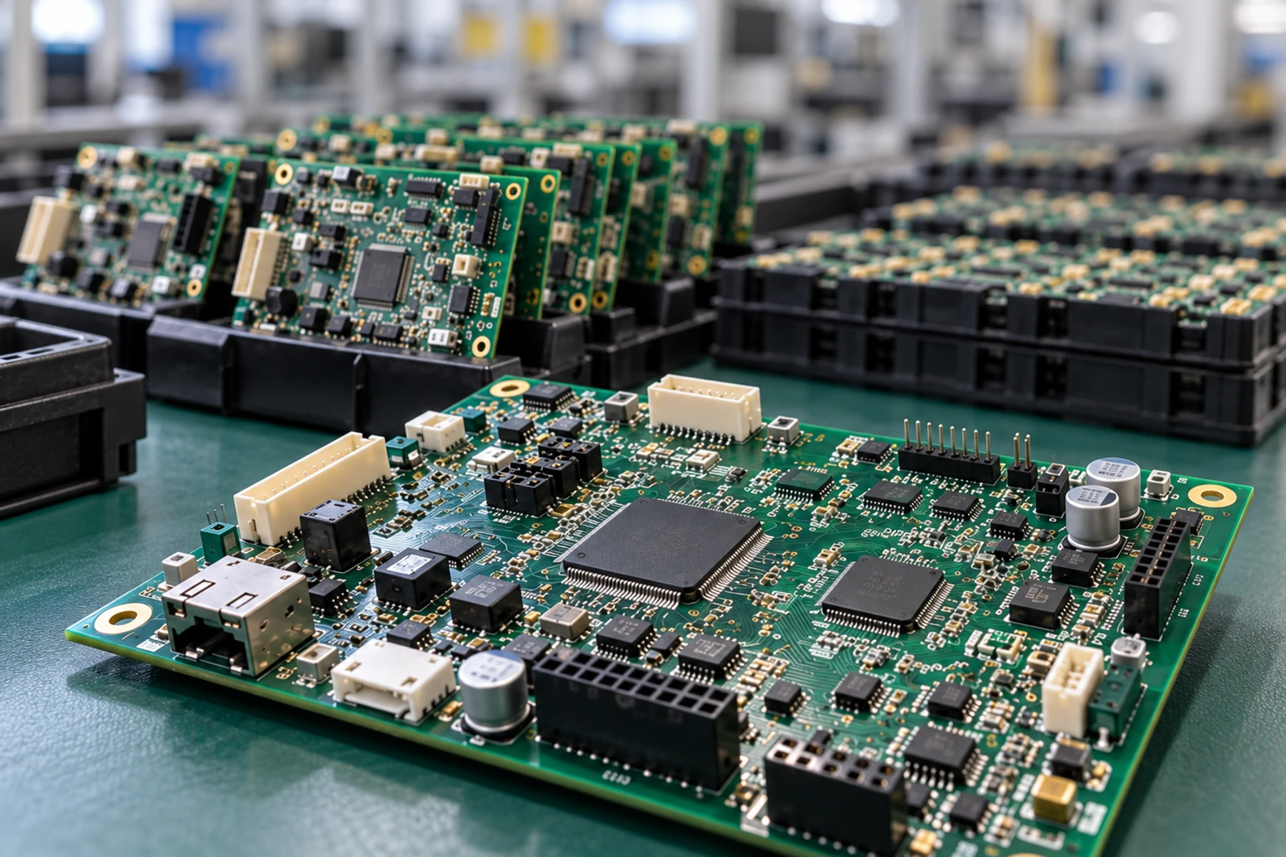
A prototype can prove that a circuit works under the conditions tested. It does not show that the design can be built repeatedly, sourced reliably, tested consistently, and released without revision confusion. Production-ready PCBA requires a controlled manufacturing baseline, not simply a larger order.
That baseline connects an approved design, a buildable BOM, synchronized fabrication and assembly files, measurable test requirements, and formal release control. If one remains informal, repeat production can expose issues that a hand-supported prototype never revealed.
This guide shows engineering, procurement, quality, and manufacturing teams how to move double-sided or multilayer rigid PCB projects through SMT, THT/DIP, or mixed-technology assembly, close pilot risks, and release a repeatable PCBA baseline.

When Is a Working Prototype Ready for Production?
A Working Prototype Proves Function, Not Repeatable Manufacturability
A prototype shows whether the design performs under the conditions tested. Production readiness asks whether the manufacturing system can reproduce that result:
- Can the PCB be fabricated within a stable, documented process window?
- Can every component be purchased in the required quantity from an acceptable source?
- Can the assembly be built without manual corrections that exist only in an engineer’s memory?
- Can inspectors and test operators make the same pass/fail decision from written criteria?
- Can the correct design, firmware, test program, and work instructions be identified later?
During development, engineers may replace a component, add a jumper, revise firmware, or rework a difficult joint. Before production release, those interventions must be incorporated into the controlled BOM, drawings, assembly data, firmware, and test instructions.
Production readiness begins when the product no longer depends on undocumented intervention.
Readiness Depends on Build Quantity, Process, Supply, Test, and the Approved Revision
No build quantity proves production readiness by itself. A 100-unit build can still contain an unapproved substitution or incomplete test specification, while a smaller, lower-risk pilot may produce enough evidence for a controlled release.
Judge readiness by evidence. It should show that:
- the selected manufacturing process can repeat the required result;
- the BOM can support the planned production horizon;
- defects and deviations from the pilot have been resolved or formally accepted;
- inspection and functional testing have defined acceptance criteria; and
- all released files carry matching revision identifiers and approvals.
Define the Target Build Stage, Quantity, and Release Criteria
Separate Engineering Prototype, Validation Build, Pilot Build, and Repeat Production
Build stages serve different purposes. Calling every small order a prototype can obscure whether the supplier should expect engineering flexibility or production-level controls.
| Build stage | Primary purpose | Typical evidence needed before release |
|---|---|---|
| Engineering prototype | Prove core design functions and identify design errors | Buildable design files, provisional BOM, basic bring-up plan |
| Validation build | Verify the revised design against product requirements | Controlled revision, validation plan, documented results and open issues |
| Pilot build | Confirm manufacturing, inspection, test, traceability, and supply readiness | Production-intent files, process review, test limits, deviation controls |
| Repeat production | Reproduce the approved baseline under change control | Approved release package, purchasing authorization, quality and test records |
For each stage, state what the build must prove, which inputs are production-intent, and what remains provisional.
Assign Approval Owners and Measurable Exit Criteria for Each Release Gate
Assign an owner to each gate. Design engineering approves the design baseline; supply chain and engineering address sourcing risk; quality approves inspection and test criteria; and the customer or product owner approves deviations that affect form, fit, function, compliance, or reliability.
Replace statements such as “sample looks good” or “testing passed” with measurable exit criteria:
- all critical functions tested within documented limits;
- no unresolved safety-critical or function-blocking defects;
- all pilot deviations assigned a disposition and owner;
- BOM manufacturer part numbers and approved alternatives confirmed;
- released PCB, assembly, firmware, and test revisions matched; and
- required records linked to the relevant serial number or production lot.
Replace Prototype-Only Parts and Close BOM Risk
Remove Development Modules, Temporary Wiring, and Unavailable Parts
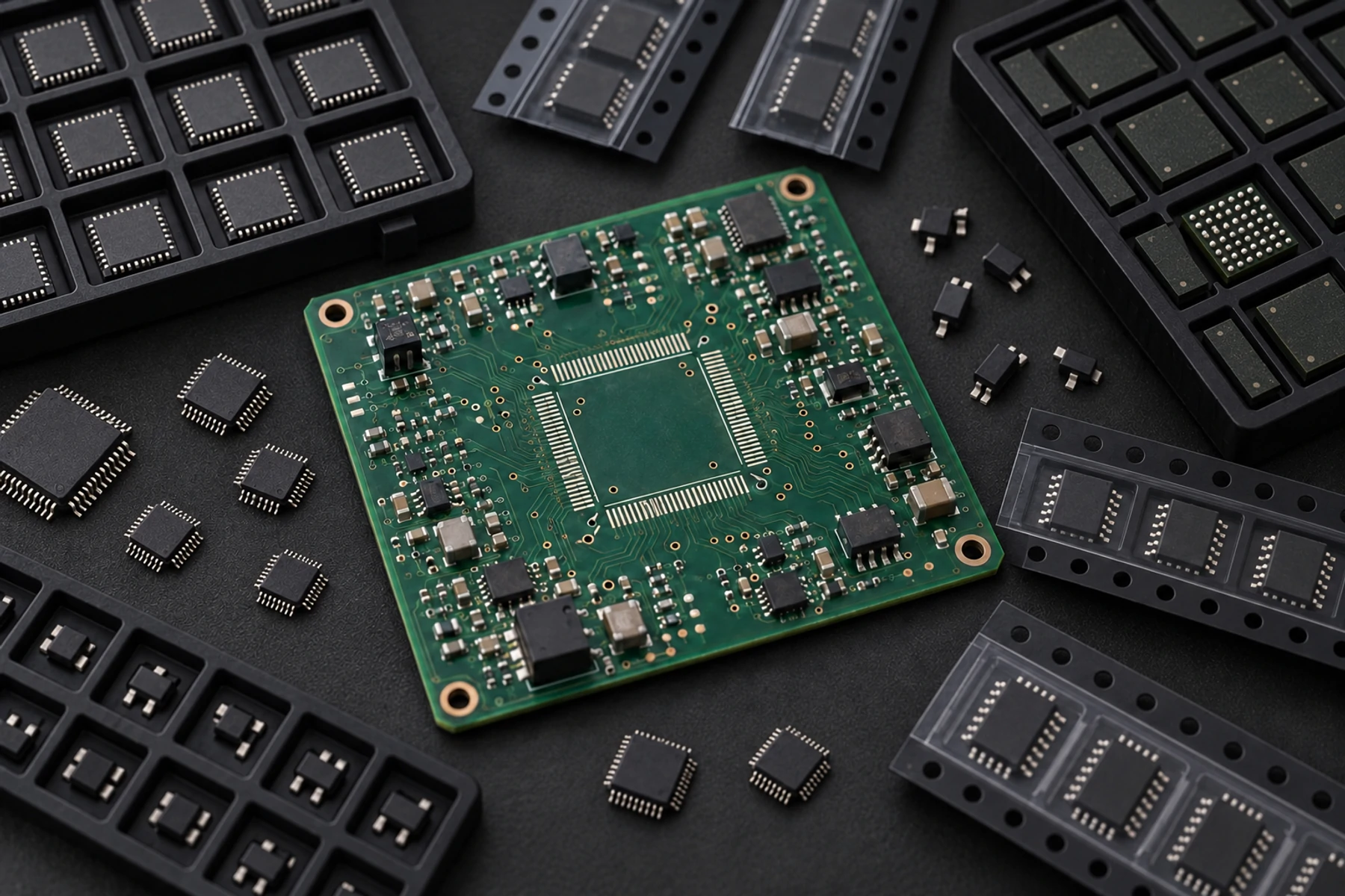
Prototype hardware may include evaluation modules, socketed parts, hand-wired connections, substitutes, or lab-stock components. Before the pilot, replace these temporary solutions with production-intent choices and update the schematic, layout, BOM, assembly drawings, and test instructions together.
Flag parts that change the assembly route. A post-reflow connector, manually installed wire, or heat-sensitive device may require another operation, special tooling, or a separate inspection point, affecting both quotation accuracy and repeatability.
Review Lifecycle Status, Lead Time, Single-Source Risk, and Approved Alternatives
A functional BOM is not automatically a production BOM. Review each critical line for:
- manufacturer and exact manufacturer part number;
- lifecycle status and recent change notices;
- realistic lead time at the planned quantity;
- approved purchasing channels and traceability needs;
- single-source or allocation exposure;
- minimum order and excess-inventory implications; and
- technically qualified alternatives.
Do not use “or equivalent” in place of engineering approval. An alternate part may affect electrical, thermal, mechanical, firmware, soldering, test, or compliance requirements. A nominal form-fit-function match is not enough when qualification or test evidence changes. Define who may propose it, what evidence is required, and who approves it before purchase or assembly.
Within a PCBA project, SUNHOPE may coordinate approved procurement under a turnkey, partial-turnkey, or customer-consigned model. SUNHOPE may identify risk and propose alternatives, but no manufacturer part number changes without customer approval. See electronic component obsolescence management for PCBA projects for the closed-loop review process.
Release One Controlled PCB and Assembly File Package
Align Gerber or ODB++ Data, Drill Files, Fabrication Drawings, and Stack-Up Requirements
The PCB fabrication package should define one buildable revision without requiring the fabricator to reconcile conflicting sources. Double-sided and multilayer rigid PCB projects need complete material, finish, dimensional, and panel requirements; multilayer designs also need an approved stack-up. Depending on the project, include:
- Gerber or ODB++ data;
- NC drill and route files;
- fabrication drawing with dimensions, tolerances, and notes;
- layer stack-up and controlled-impedance requirements;
- material, copper weight, surface finish, solder mask, and legend requirements;
- panelization instructions or approved panel constraints; and
- applicable acceptance class or project-specific criteria.
Use the same revision on the drawing, electronic data, and purchase order. Remove superseded files and state which source controls if one fabrication note intentionally overrides another.
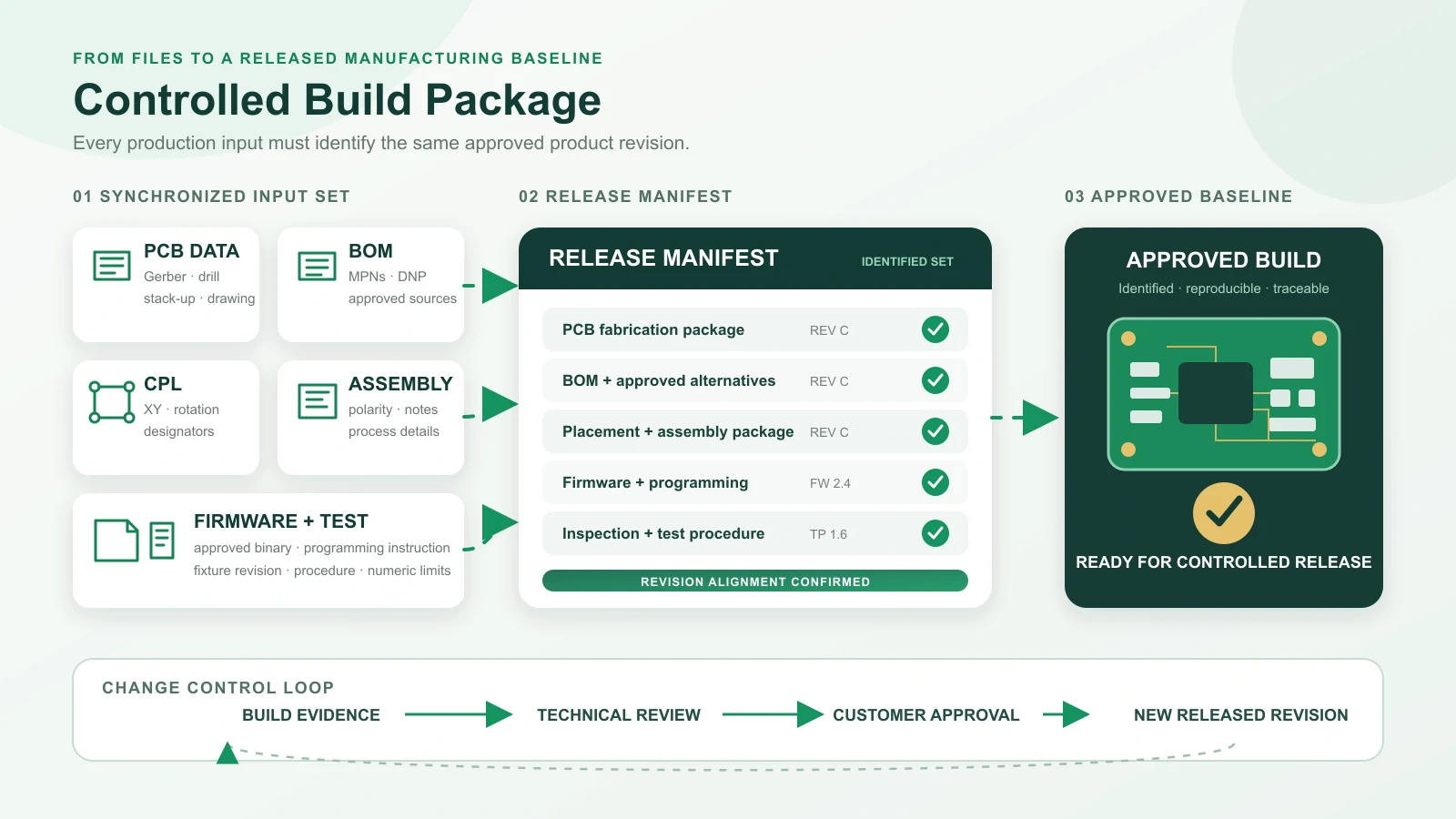
Align BOM, CPL, Assembly Drawings, Polarity Notes, and Revision Identifiers
The assembly package should represent the same product revision. Align the BOM, component placement list or centroid file, assembly drawings, orientation notes, approved substitutions, and special process instructions.
Confirm that each populated reference designator appears consistently in the BOM, placement data, and drawing. Mark do-not-populate positions and resolve duplicate, missing, or obsolete designators before release.
Use a release manifest listing each file, revision, release date, owner, and approval status. This helps the PCBA manufacturing support team identify missing inputs and prevents an old attachment from becoming the production baseline.
Close DFM and DFA Issues Before the Pilot Build
Resolve Fabrication, Solderability, Placement, Panelization, and Assembly-Access Issues
Complete DFM and DFA reviews before fixing the pilot schedule. The review should identify features that increase variation, defects, cost, or dependence on manual work while preserving the product’s functional requirements. Close each finding before material commitment where practical.
Review items such as:
- trace, spacing, annular ring, drill, routing, and copper-to-edge constraints;
- solder mask and paste openings;
- component-to-component and component-to-edge clearance;
- polarity, pin-one, and bottom-side orientation visibility;
- thermal-pad and via arrangements that influence soldering;
- board support, fiducials, tooling areas, and panel strength;
- access for programming, inspection, connectors, and test probes; and
- mixed-technology sequencing for SMT and THT/DIP assembly.
Each DFM finding needs a disposition: update the design, accept the risk, change the process, or request more evidence.
Record Accepted Exceptions and the Owner of Each Disposition
When a recommendation cannot be adopted because of electrical, mechanical, certification, schedule, or legacy constraints, record the feature, risk, agreed control, approver, and revision.
This prevents the issue from returning in later quotations or being changed by a team that does not know why the feature was retained.
Define Programming, Inspection, and Functional Test Requirements
Provide Firmware, Programming Method, Inspection Scope, and Test Inputs
Provide the released firmware binary, checksum or other identity control, programming interface, configuration data, security instructions, and a method for confirming the programmed version.
Define what each inspection or test is intended to detect. Visual inspection, AOI, X-ray, bare-board electrical test, ICT, and functional test provide different coverage; the appropriate combination depends on package type, access, project risk, quantity, and product requirements. No single method replaces product-specific functional acceptance.
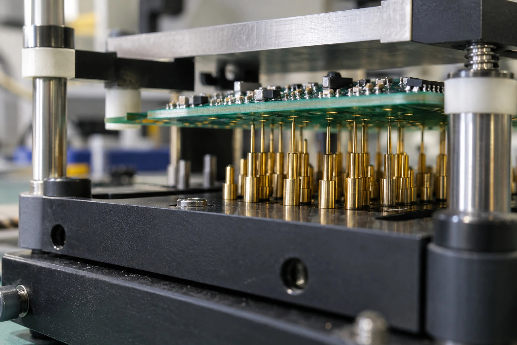
For functional testing, specify operating modes, power conditions, interfaces, loads, stimuli, expected outputs, stabilization times, and safe power sequences. Identify any customer-supplied fixture, cable, mating product, software, or reference unit.
For quotation inputs, see PCBA functional test requirements.
Set Numeric Acceptance Limits, Records, and Failed-Board Handling Rules
Replace instructions such as “check that the output is normal” with numeric limits, units, tolerances, operating conditions, and recording rules tied to the board or lot.
Also decide what happens after a failure:
- Is retest allowed before diagnosis?
- Who can authorize repair or component replacement?
- How many repair attempts are permitted?
- Must the full test sequence run again after rework?
- Which failure evidence must be retained?
- When does a repeated defect trigger containment or production stop?
These rules make pilot evidence consistent and support release decisions. Align them with the PCB and PCBA quality assurance process.
Use First Article and Pilot Production as Release Gates
Define First Article Evidence and Pilot Objectives Based on Project Risk
A first article verifies that initial output matches the released package before the full lot proceeds. Evidence may include dimensions, component identity and orientation, workmanship, firmware identity, electrical and functional results, and agreed photographs.
A pilot build evaluates the wider production system, including material flow, process sequence, inspection, test stability, work instructions, records, packaging, and repeatability across multiple boards.
Set pilot objectives from project risk. Fine-pitch or hidden joints, high-current paths, unusual materials, manual operations, planned volume, and end-use consequences may require different evidence from a mature, low-complexity design. State the evidence required for release and who accepts any residual risk.

Do Not Treat One Fixed Sample Size as Proof of Production Readiness
No universal pilot quantity proves readiness. The required evidence depends on design complexity, defect severity, process maturity, expected volume, and the confidence needed for release.
Choose quantity after defining the pilot objective. Fixture validation needs enough boards and operating conditions to expose repeatability problems; a manual soldering concern may require observation across relevant operators or shifts; material variation may require more than one lot when practical.
Document the rationale. Quantity supports the release decision; it does not replace it.
Turn Pilot Results Into Corrected and Approved Files
Review Yield, Defects, Rework, and Deviations
Review first-pass results separately from boards that passed after rework or retest. Where evidence permits, classify defects by design, fabrication, component, placement, soldering, programming, test method, handling, or documentation.
Evaluate every deviation. A pilot that succeeds only after an operator adjusts placement, adds solder, changes a test threshold, or uses a substitute part has exposed a release issue that must be controlled.
Link Each Corrective Action to an Updated and Approved Revision
A corrective action is complete only when it updates the affected controlled item, such as the PCB layout, BOM, placement file, assembly drawing, work instruction, firmware, fixture, test program, or packaging specification.
For each issue, record:
- the observed defect or deviation;
- the evidence and suspected or confirmed cause;
- the containment applied to the current lot;
- the corrective action for future builds;
- the affected files and revisions; and
- the verification result and approver.
This closed loop prevents a shop-floor fix from becoming a recurring production problem.
Anonymized Pilot-Build Case: Resolving an Intermittent Relay-Output Failure
This anonymized case is based on an actual customer project. Identifying and commercially sensitive details have been omitted while preserving the technical sequence and release decisions.
Project and Release Risks
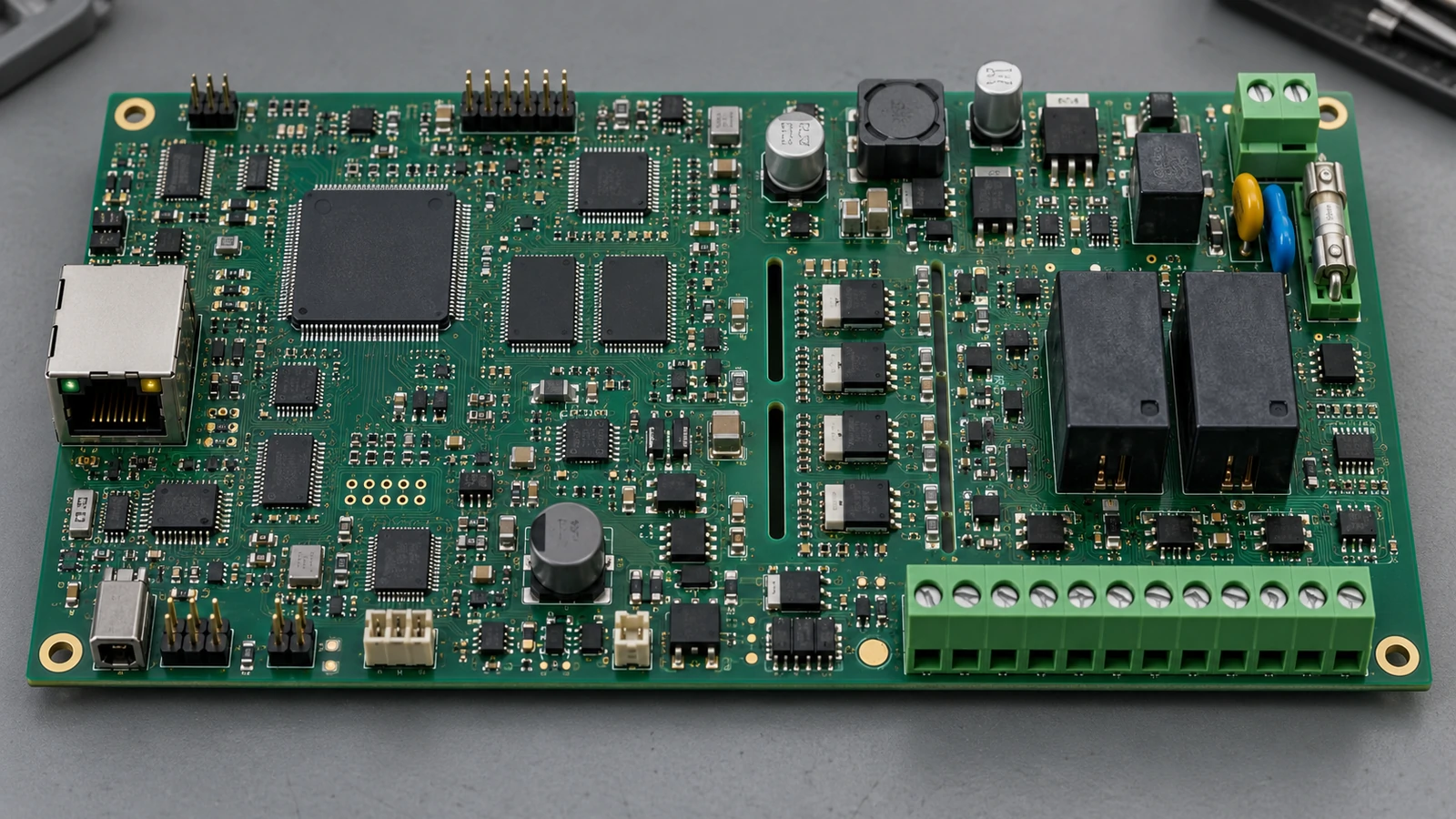
An industrial control product used a six-layer rigid PCB with a controlled-impedance communication interface, double-sided SMT, and THT connectors and relays. Under a partial-turnkey model, SUNHOPE manufactured the PCB, procured the approved balance of components within the PCBA project, assembled the boards, and performed the agreed inspection and functional test. The customer supplied controlled devices, firmware, and the product-specific fixture.
The initial review identified four release risks:
- the PCB drawing and assembly package carried different revision identifiers;
- two BOM lines lacked exact manufacturer part numbers, approved alternatives, or a do-not-substitute decision;
- a bottom-side SMT device restricted the planned selective-solder pallet opening around a THT connector; and
- the functional test lacked the load, stabilization time, voltage limits, and retest rule for the relay output.
SUNHOPE returned one findings list before material commitment. The customer synchronized the package, confirmed the exact part numbers, and approved one qualified alternative after technical review. No substitution was made without approval. The teams also agreed on the fixture interface, numeric limits, test sequence, and release evidence.
Pilot Finding and Evidence
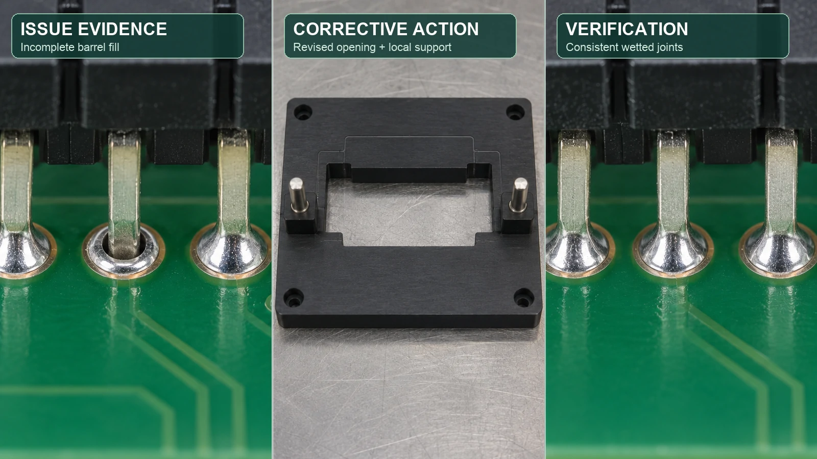
During the pilot, bare-board electrical test, AOI, selected X-ray evidence, and firmware records showed no related upstream anomaly. Functional testing under the specified load found intermittent relay output in a subset of the pilot lot. Because the symptom appeared under load, the team continued with process and interconnect analysis.
The team contained the affected assemblies and preserved serial-linked test logs. Review of the THT area, solder-joint evidence, process records, and pallet geometry isolated the problem to high thermal mass at one connector joint combined with restricted solder access through the original pallet opening. The evidence did not support changing the relay, making an unapproved substitution, or treating the symptom as a firmware issue.
Containment and Corrective Action
Affected boards were segregated, repaired under an approved instruction, and subjected to the full functional test again. The corrective action revised the pallet opening and local support, adjusted documented soldering parameters within the approved process window, and added a focused inspection point.
The customer approved a minor placement adjustment for the next PCB revision. SUNHOPE updated the assembly drawing, work instruction, inspection record, and manufacturing inputs; the customer updated the controlled design files and release manifest. Design authority remained with the customer while manufacturing evidence drove the change.
Verification and Release
A confirmation build used the corrected PCB and assembly package, approved BOM, revised pallet, controlled process parameters, and completed test procedure. It met the agreed first-article and pilot-release criteria, including the loaded relay-output test. The released baseline linked the PCB data, BOM, placement file, assembly drawing, firmware, test procedure, fixture revision, and packaging instruction.
The confirmation build closed the evidence chain from PCB fabrication and assembly through testing, customer approval, and revision-controlled release.
Freeze the Production Baseline and Control Later Changes
Freeze the Approved BOM, Fabrication, Assembly, Firmware, and Test Package
After pilot actions are closed, freeze a production baseline that identifies the approved versions of:
- schematic and PCB design;
- fabrication data, drawing, and stack-up;
- BOM and approved alternatives;
- placement data and assembly drawings;
- firmware and configuration data;
- inspection criteria, fixture, and test program;
- work instructions and accepted exceptions; and
- labeling, traceability, packaging, and delivery requirements.
Give the release a unique identifier and retain its approval record so the supplier and customer can determine which package governed each production lot.
Reassess Readiness After Material, Process, Design, or Test Changes
A frozen baseline does not prevent change; it gives each change a visible review and approval path.
Classify each change by its effect on form, fit, function, reliability, manufacturability, supply, compliance, firmware, and test coverage. A documentation correction may need file review only; a component substitution may require engineering analysis and focused testing; a layout, laminate, soldering, firmware, or fixture change may require a new first article or pilot activity. A previous build does not qualify a materially changed product.
Define Traceability, Packaging, and Delivery Requirements
Specify Serial or Lot Traceability, Labels, Records, and Retention Period
Match traceability to the decisions you may need to make later. Define board-level serial numbers, lot-level records, or both, and connect data such as:
- PCB lot and assembly lot;
- critical component lot or date code;
- BOM and design revision;
- firmware and test-program revision;
- inspection, test, repair, and retest result;
- production date or line; and
- shipment or customer order.
Define label content, format, placement, and readability, plus who retains each record, for how long, and in what retrievable format. Records should be searchable by the agreed serial or lot identifier.
Define ESD, Moisture Protection, Packing, and Delivery Requirements
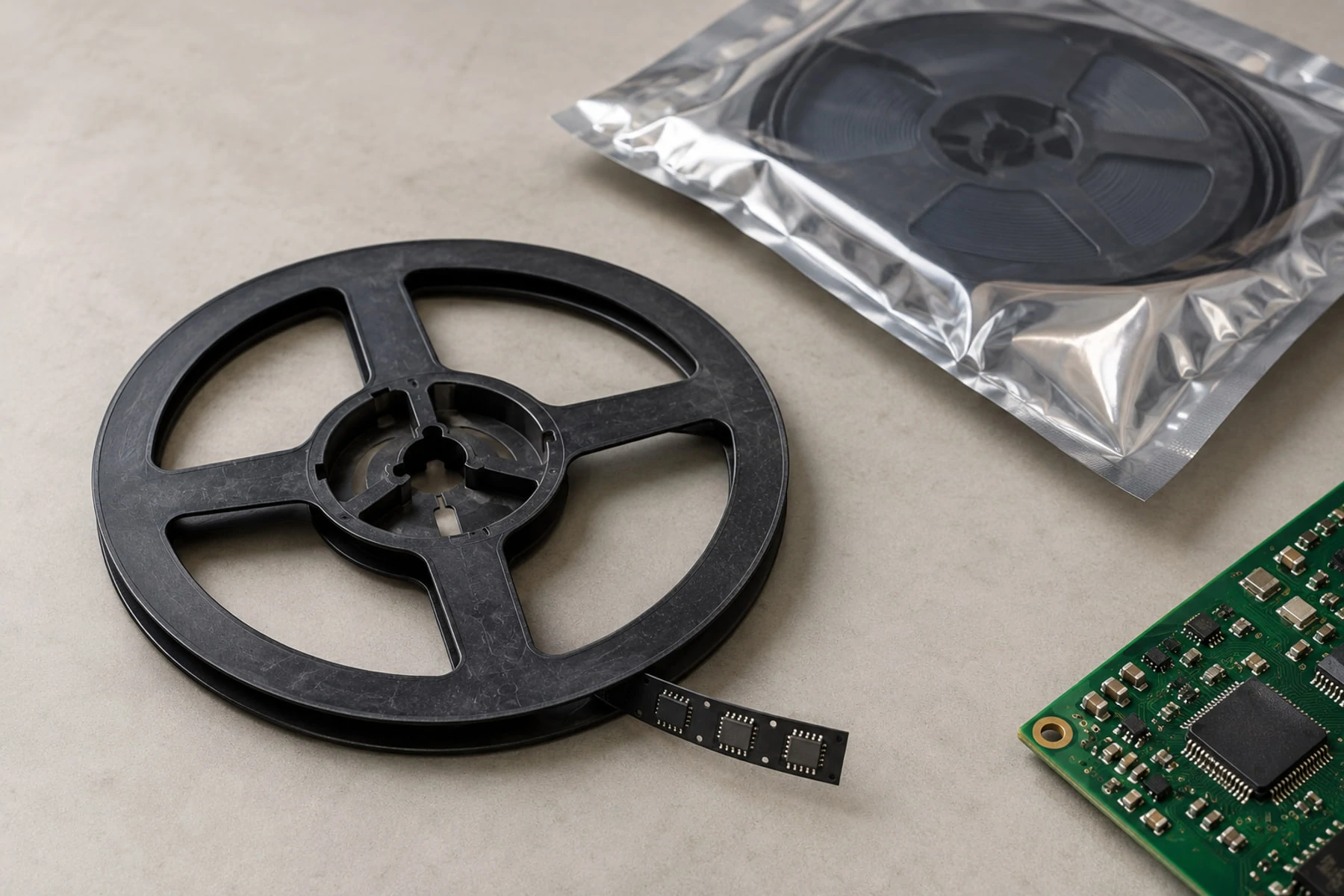
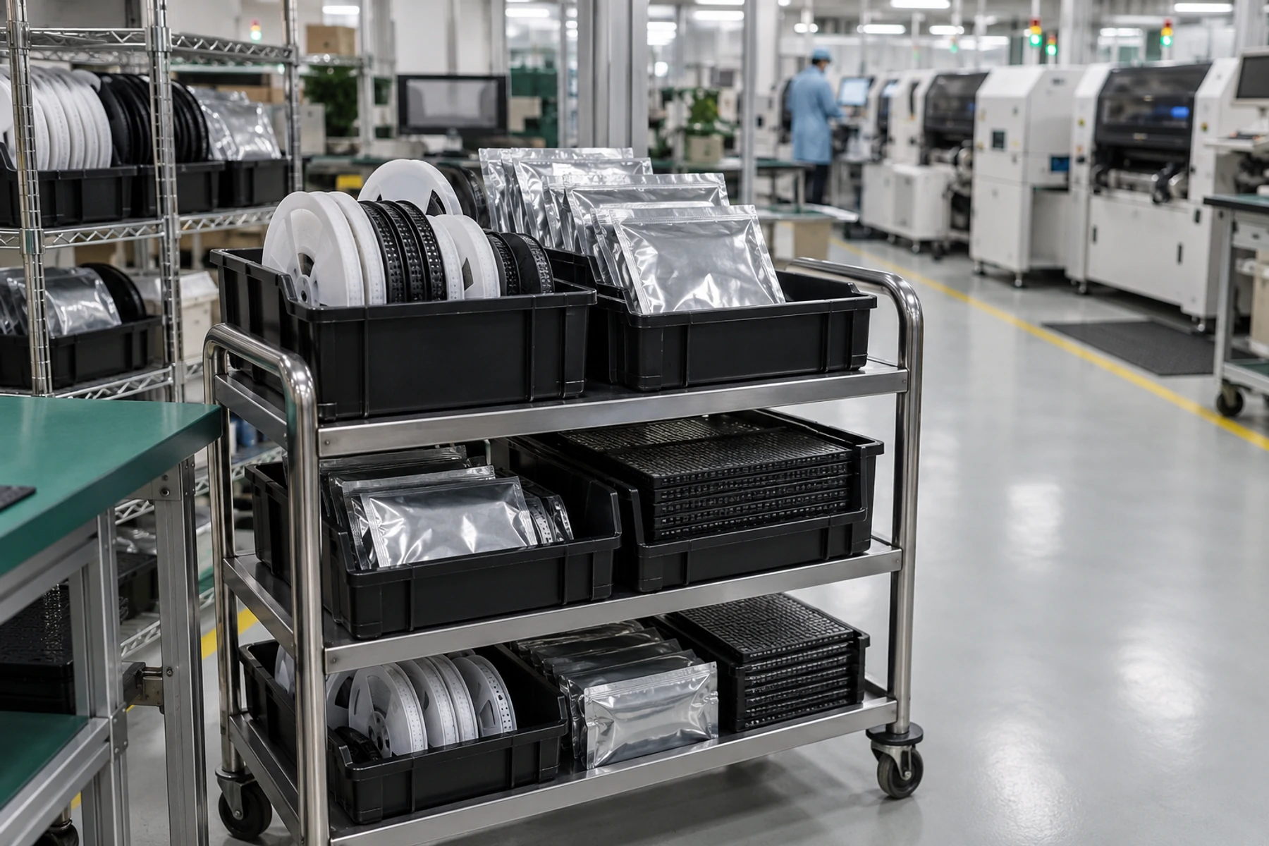
Treat packaging as part of the release. Define ESD protection, moisture controls where applicable, board separation, connector or pin protection, cleanliness, labels, carton quantity, and transport constraints.
For assemblies feeding a downstream line, define tray orientation, pack quantity, barcode rules, and receiving requirements before the pilot shipment. Review the supplier’s PCBA technical capabilities and packaging controls against the product rather than assuming a generic method will fit.
Prototype-to-Production Readiness Checklist
Use the gate table to keep approval evidence and change impact visible during quotation, pilot release, and later change review. Adapt owners and criteria to the organization and product risk.
| Release gate | Owner | Required evidence | Example exit criteria | Reopen the gate when… |
|---|---|---|---|---|
| Product requirements | Product or systems owner | Requirements and critical characteristics | Functions and acceptance conditions defined | Intended use or a critical requirement changes |
| Design release | Design engineering | Schematic, layout, calculations, reviews | No unresolved function-blocking issue | Circuit, layout, interface, or mechanical changes |
| BOM readiness | Supply chain and engineering | Lifecycle, source, lead-time, and alternate review | Critical MPNs and approval paths defined | Part, source, lifecycle, or forecast changes |
| PCB package | PCB engineering | Fabrication files, stack-up, panel requirements | Files synchronized and revision-controlled | Material, stack-up, routing, finish, or panel changes |
| Assembly package | Manufacturing engineering | BOM, CPL, drawings, process notes | Designators, polarity, DNP, and special operations align | Component, footprint, placement, or assembly-route changes |
| DFM/DFA closure | Engineering and supplier | Findings and dispositions | Each finding is corrected or formally accepted | Design or manufacturing process changes |
| Programming and test | Test engineering | Firmware, fixture, procedure, limits, records | Repeatable tests with measurable pass/fail limits | Firmware, fixture, test program, or coverage changes |
| First article | Quality and engineering | Initial-unit inspection and test record | Initial output matches released package | Defined change requires renewed approval |
| Pilot release | Cross-functional owner | Yield, defects, rework, deviations, actions | Actions are closed or accepted with owners | New material risk in pilot evidence |
| Production baseline | Configuration owner | Approved release manifest | Complete baseline frozen and distributed | Any controlled item changes |
| Traceability and delivery | Quality and logistics | Label, records, packaging, delivery approval | Records and packs meet receiving requirements | Label, retention, packaging, or route changes |
Before requesting a repeat-production quotation, send SUNHOPE the released package, target quantity, sourcing model, test scope, traceability requirements, and open technical questions for a PCB and PCBA manufacturing support review. A structured review should close ambiguity before material commitment and pilot scheduling.
Frequently Asked Questions
What Files Are Required to Move from a PCB Prototype to PCBA Production?
Provide one synchronized revision of the PCB fabrication files, BOM, placement data, assembly drawings, firmware and programming instructions, inspection and test requirements, and packaging and traceability specifications. Include a release manifest so each file can be verified.
Is a Successful Prototype Enough to Request Repeat Production?
No. It proves that at least one build worked under the conditions tested. Confirm manufacturability, BOM availability, test criteria, pilot results, approved revisions, and change-control responsibilities before repeat production.
How Many Units Should Be Included in a PCBA Pilot Build?
There is no universal number. Base the quantity on the pilot objective, design complexity, process maturity, expected volume, defect consequences, and evidence required for release. Record the rationale rather than treating a standard number as proof.
What Is the Difference Between a First Article and a Pilot Build?
A first article verifies initial output against the released package before the full lot proceeds. A pilot build evaluates whether materials, assembly, inspection, testing, records, and packaging can deliver repeatable results across the wider production system.
What Changes Should Trigger Another First Article or Pilot Review?
Reassess after changes to the PCB design, material, stack-up, critical component, footprint, assembly process, firmware, fixture, or test program. Set the review scope from the potential effect on function, reliability, compliance, and process repeatability.