A request such as “include functional testing” is not enough for a reliable PCBA quotation. The supplier still needs to know which functions must be verified, under what conditions, with which equipment and fixture, against which limits, and what record must be retained. Until these inputs are closed, cost, lead time, cycle time, and test coverage remain provisional.
Functional testing should therefore be treated as an engineered production process. The buyer owns the product requirements and acceptance intent; the assembly supplier translates those requirements into a controlled test flow, identifies manufacturing and access constraints, and records results against the approved revision. This guide explains the information both parties should close before quotation, fixture release, pilot validation, and volume production.
What Must Be Defined Before a Functional Test Can Be Quoted
Release One Product and Test Baseline
The quotation package must describe one identifiable product revision. At minimum, align the PCB fabrication data, BOM, component placement data, assembly drawings, firmware, programming instructions, product specification, and functional test requirements. If the hardware or firmware is still changing, identify the working revision and the date or gate at which it will be frozen.
A consistent baseline also connects functional testing to the wider prototype-to-production readiness process. A board cannot be released for repeat production if the test program proves one firmware version while purchasing, fabrication, or assembly uses another.
Provide the Information That Drives Cost and Schedule
A useful request for quotation states what the supplier must provide. These items determine whether a bench setup is sufficient or the project needs a production fixture, automated instruments, software, calibration, specialist support, and added validation:
- Product scope: board revision, annual and order quantities, build stage, target test quantity, and expected production life.
- Test intent: functions, modes, interfaces, loads, stimuli, expected outputs, numeric limits, and known exclusions.
- Programming: firmware files, revision identity, configuration data, programming interface, security controls, and post-program verification.
- Equipment and access: fixture concept, mating connectors, test points, reference units, instruments, cables, adapters, power supplies, and safety controls.
- Deliverables: fixture, source code or executable, drawings, validation evidence, test logs, failure codes, maintenance instructions, and record-retention period.
- Commercial responsibility: customer-supplied items, supplier-developed items, third-party services, non-recurring engineering charges, ownership, and transfer conditions.
Identify Open Items and Requotation Triggers
Not every input must be final at the first quotation, but every open item should be visible. The supplier can quote against stated assumptions and review the price or schedule when they change. Typical triggers include a new hardware or firmware revision, added functions, tighter limits, new interfaces, more records, a shorter cycle-time target, a changed fixture concept, or delayed customer-supplied equipment.
What Functional Testing Verifies and What It Does Not
Verify Only Defined Functions Modes and Conditions
A functional test applies defined inputs and operating conditions to an assembled board, then compares observable outputs with approved acceptance limits. Depending on the product, it may confirm power rails, current consumption, digital and analog channels, communication interfaces, sensors, actuators, relays, programmed identity, or a controlled operating sequence.
A pass proves only that the unit met the approved requirements under the defined conditions. It does not establish long-term reliability, environmental endurance, regulatory compliance, complete fault coverage, or every end-use condition. Those claims require separate evidence and, where applicable, qualified laboratories or product-level validation.
Use Each Inspection and Test Method for Its Intended Evidence
Inspection and electrical test methods are complementary. The appropriate combination depends on the design, package types, access, risk, volume, and customer requirements; it should not be assumed that every method is included in every PCBA quotation.
| Method | What it can verify | What it cannot prove alone |
|---|---|---|
| Visual inspection or AOI | Presence, polarity, orientation, visible solder and placement conditions within the method’s capability. | Electrical function, hidden joints, firmware behavior, or loaded performance. |
| X-ray inspection | Internal features such as hidden solder joints, voiding, bridges, or alignment where the image and criteria permit. | Complete electrical performance or all workmanship conditions. |
| ICT or flying probe | Accessible nets, shorts, opens, component values, and selected device checks according to the program and access. | Full product behavior under operating loads or interfaces. |
| Functional test | Defined board behavior under specified power, stimuli, interfaces, loads, sequences, and limits. | Untested modes, life expectancy, environmental robustness, or regulatory compliance. |
Workmanship acceptance may reference IPC-A-610J, but the customer and supplier must still agree the class, revision, contractual precedence, and any product-specific criteria. A workmanship standard does not define the product’s functional limits.
Keep Product Qualification and Compliance Outside the Production Test Claim
Production functional testing may support a qualification plan, but it is not certification. EMC, safety, environmental, life, stress, or system qualification can require different samples, conditions, methods, and authorities. State whether SUNHOPE is executing a released test, supporting qualification samples, coordinating a specialist, or supplying manufacturing records for the customer’s compliance process.
Build a Function to Test Coverage Matrix
Map Each Function to a Stimulus Measurement Limit and Record
A function-to-test coverage matrix converts a product specification into an executable production plan. Each row should identify the function, test access, operating condition or stimulus, measured response, numeric acceptance limit, equipment, and retained record. The matrix also reveals where the fixture, firmware, and board design must work together.
| Function and access | Stimulus and condition | Measurement and acceptance | Record and failure identity |
|---|---|---|---|
| Input power through production connector | 24 VDC at defined tolerance; controlled current limit; specified startup state | Input current and regulated rails after stated settling time; limits in V and A | Serial number, supply setting, measured values, step result, program revision |
| MCU and firmware through programming or debug interface | Released image, configuration file, programming voltage, approved sequence | Programming status, checksum or version identity, protected-state check if required | Firmware ID, programmer ID, timestamp, pass/fail and error code |
| RS-485 through mating connector | Defined baud rate, addressing, termination, command set, and cable condition | Valid response, message content, timeout, and error criteria | Command result, response value, timeout or communication error code |
| 0–10 V analog input through fixture source | Approved low, nominal, and high input points after warm-up | Converted value within stated tolerance at each point | Applied stimulus, measured result, limit, channel, fixture nest |
| Controlled load output through protected load path | Defined command, load, duration, duty cycle, and safe discharge sequence | Output state, voltage/current, response time, and fault status | Load condition, measured result, step result, failure category |
Make Coverage Gaps and Residual Risk Visible
Not every function must be tested on every unit. A feature may be covered during pilot validation, by sampling, by another method, or at system level. Mark each function as production-tested, sample-tested, otherwise verified, or not covered, and record the owner, approval, and residual risk.
Define Firmware Interfaces Loads Measurements and Limits
Control Firmware Programming and Startup Conditions
Firmware is part of the test baseline. Provide the released image, checksum or version identifier, programming interface, configuration, boot mode, security requirements, and verification method. State whether it is final, test-only, or followed by a production image, and how an interruption or verification failure is handled.
Startup conditions matter as much as the file. Specify power sequence, reset behavior, initialization time, required peripherals, default outputs, and any command that places the board into a test mode. If a board can enter more than one configuration, the retained test record should identify which configuration was exercised.
Specify Interfaces Stimuli Loads and Observable Outputs
For each interface, define the connection and protocol conditions. Communication tests may need pinout, cable, termination, baud rate, address, message, timeout, and error response. Analog tests need source accuracy, range, impedance, settling time, and measurement point. Outputs need the load, duty cycle, duration, discharge method, and protection limits. An unrealistic electrical condition can pass a board that later fails in the product.
Set Numeric Limits With Measurement Capability in Mind
Acceptance limits should be expressed with units, operating conditions, and inclusive or exclusive boundaries. The measurement system must be capable of distinguishing conforming from nonconforming units near those limits. Instrument accuracy, fixture resistance, source tolerance, resolution, noise, settling time, environmental effects, and calibration status all contribute to uncertainty.
When uncertainty is material, buyer and supplier should agree whether to apply a guard band, improve the method, or widen the product limit based on engineering evidence. The logic should be documented rather than decided by an operator after a borderline result. See Keysight’s overview of measurement uncertainty and guardbanding for the underlying decision risk.
Replace Subjective Checks With Repeatable Criteria
Instructions such as “LED looks normal,” “communication is stable,” or “output is acceptable” invite inconsistent judgments. Convert them into observable criteria whenever practical:
- Replace “power is normal” with rail values, tolerances, current limit, stabilization time, and measurement points.
- Replace “communication passes” with commands, expected responses, timeout, retry allowance, and failure code.
- Replace “output drives the load” with load condition, measured voltage or current, response time, duration, and protective shutdown criteria.
Confirm Test Access Power Up Safety and DFT
Review Test Points Connectors Grounding and Fixture Contact
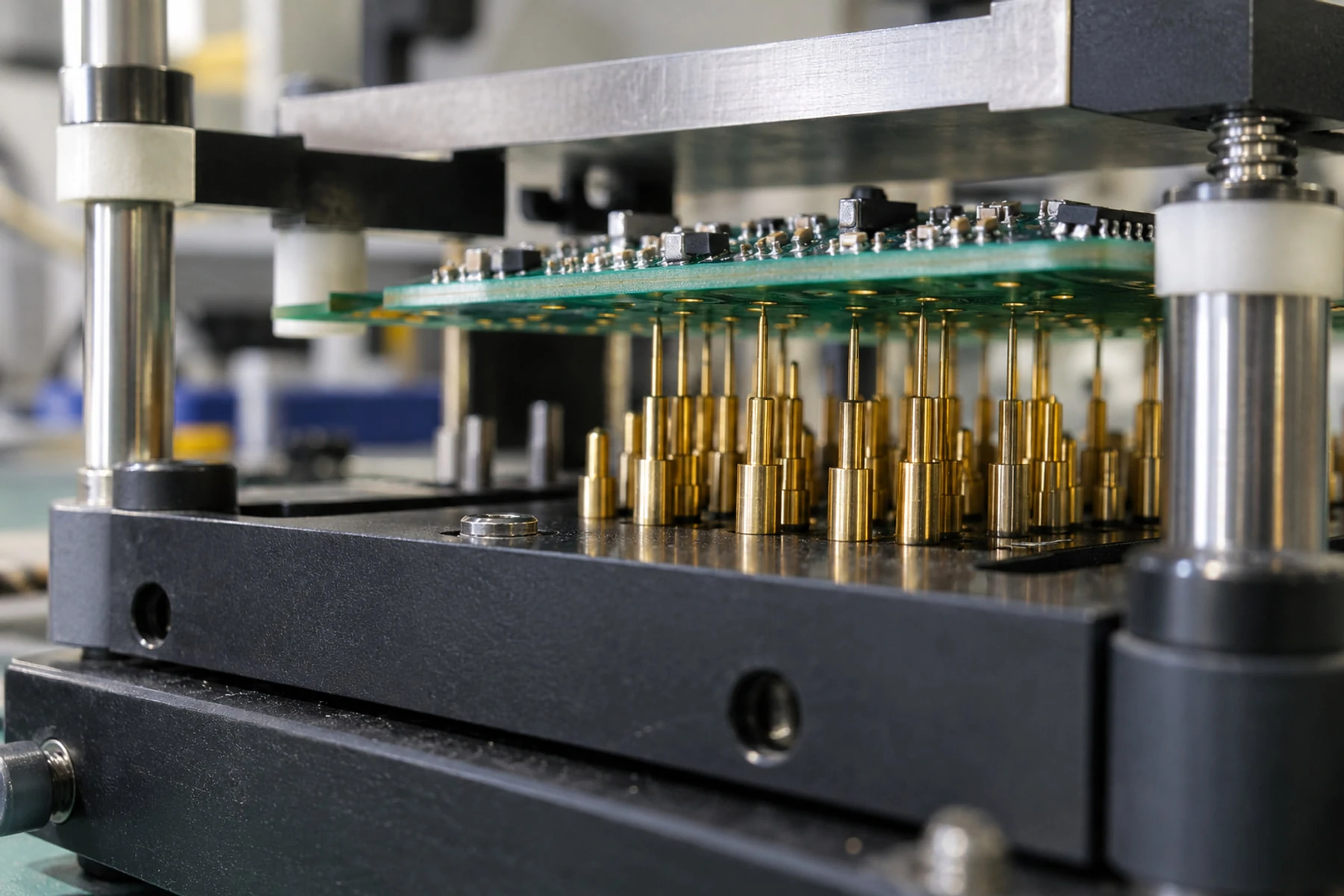
The board must expose the signals in the coverage matrix. Review test-point size, spacing, keep-outs, surface finish, fixture-side access, grounding, connector durability, mating-cycle limits, and mechanical support. Dense boards may combine pogo pins, production connectors, debug interfaces, and firmware-assisted measurement.
Fixture contact is part of the measurement path. Do not casually combine high-current returns, low-level analog references, and communication grounds. Define how contact resistance or cable drop is controlled, how worn pins are detected, and which errors identify the fixture rather than the product.
Control Power Sequencing and Operator Safety
Define safe connection, power-up, test, discharge, and removal sequences. Use current limiting, interlocks, guarding, emergency stop or safe shutdown where the hazard assessment requires them. State how reverse polarity, short circuit, charged capacitors, inductive loads, hot surfaces, stored energy, and externally powered interfaces are controlled. The production instruction should distinguish a product failure from a safety trip or fixture fault.
Close DFT Issues Before Fixture Release
A design-for-test review should occur before fixture fabrication. Each issue needs a disposition: modify the PCB, add an accessible connector or pad, change the measurement method, accept reduced coverage, or move the check to another manufacturing or system-level control. If the hardware cannot change, document the residual limitation before the customer approves fixture investment.
Agree Fixture and Test Program Scope Before Development
Choose the Delivery Model for the Project
SUNHOPE can support three delivery models. The choice should follow the buyer’s product knowledge, schedule, intellectual-property constraints, required equipment, and long-term support model rather than a fixed assumption in the assembly price.
- SUNHOPE-led development: SUNHOPE converts approved requirements into the fixture concept, electrical interfaces, test sequence, program, validation plan, production instruction, and maintenance controls. The customer supplies product requirements, released files, reference items, and approvals.
- Joint development with a specialist: SUNHOPE manages the manufacturing interface while an approved third-party supplies specialist instruments, calibrated modules, safety systems, or software. Responsibilities, data exchange, acceptance, schedule, and support must be visible to the customer.
- Customer-supplied fixture and program: SUNHOPE executes the released fixture, software, cables, procedures, limits, and reference units provided by the customer. Incoming acceptance, compatibility, training, maintenance, troubleshooting authority, and change approval still need to be defined.
Define Ownership Deliverables and Ongoing Support
Before development, agree the owner and revision of fixture drawings, wiring, BOM, mechanical files, software source or executable, instrument configuration, licenses, access controls, validation evidence, instructions, and maintenance records. State whether the fixture is dedicated, where and how long it is stored, and whether site transfer is permitted.
Separate recurring test cost from non-recurring engineering and third-party cost. Also define wear spares, maintenance, calibration or verification, change control, support, repair authority, and revalidation triggers. These details prevent a production stop from becoming an ownership dispute.
Validate the Fixture and Test Program
Challenge Both Acceptance and Failure Detection
Validation must show that the system accepts conforming boards and detects the claimed failures. Use an approved known-good unit, available boundary samples, controlled faults or simulation, repeated cycles, and multiple units and operators where practical. Correlate critical measurements with an independent reference method and document repeatability, revisions, and unresolved limits.
Also challenge missing connections, an incorrect load, communication timeout, programming error, out-of-limit measurement, fixture interlock, and record-storage failure. A pass indicator is insufficient if a step can be skipped or a result attached to the wrong serial number.
Anonymized Representative PCBA Functional Test Case: Eliminating Fixture-Induced False Failures
This anonymized representative case combines SUNHOPE’s confirmed PCB, PCBA, fixture-development, test-program integration, and production-test support scope. It identifies no customer and claims no unverified yield, cost, or reliability result.
Project and Quotation Scope
The product was an industrial control and data-acquisition PCBA built on a four-layer rigid PCB with double-sided SMT and THT terminal and communication connectors. The board accepted 24 VDC input, used an MCU with released production firmware, communicated over RS-485, measured a 0–10 V analog input, and controlled a protected load output. The customer supplied the product requirements, firmware, message definitions, and initial test logic. SUNHOPE was responsible for the production fixture and test flow, while a specialist third party supplied and calibrated a programmable signal-and-load module.
Before quotation, the parties agreed test quantity, measurement points and limits, fixture ownership, approvals, third-party scope, records, and change triggers. Development cost and recurring test time were therefore tied to approved requirements rather than “function test every board.”
Pilot Failure Pattern and Evidence
During pilot validation, the system reported intermittent analog limit failures and occasional RS-485 response errors; several units passed on retest. The team preserved the first result and compared serial, fixture nest, program revision, test step, load-switch timing, value, and bench result. A known-good unit also fluctuated on the same nest, while suspect units passed the controlled bench method.
Confirmed Cause and Corrective Action
Evidence pointed to the test path. The fixture shared part of the high-current load return with the low-level analog reference. Ground-pogo contact resistance varied across insertions, and the program sampled too soon after switching the load. The transient offset could cross the analog limit and briefly disturb the RS-485 reference.
SUNHOPE added redundant ground contacts, separated load return from measurement reference, added a fixture self-check, and introduced a justified settling interval. The program separated fixture-contact errors from product-measurement failures. Drawing, wiring, software, instruction, and maintenance plan changed under one revision.
Validation and Production Release
The revised system was challenged with the known-good unit, boundary conditions, controlled faults, repeated insertions, multiple serials, and different operators. Analog readings were correlated with an independent calibrated bench method, and RS-485 timeout and invalid-response paths were verified. Release followed customer approval of the evidence and residual coverage limits.
The retest rule allowed one controlled recovery after inspection and reseating only for a fixture-contact code; the first event remained recorded. A product-measurement failure required isolation, an approved repair decision, verification of the affected function, and the complete final test. Repeated errors by nest, code, lot, or revision triggered escalation.
Control Production Test Records Failure and Retest
Set Test Quantity Cycle Time and Capacity
State whether testing applies to every unit, a defined sample, or a risk-based combination. Sampling must identify the plan, lot, selection, acceptance, escalation, and approval. For 100 percent testing, cycle time must include loading, scanning, programming, stabilization, measurement, unloading, records, and failure handling—not only the automated sequence.
Capacity should be reviewed against the order profile and maintenance plan. A single long-cycle fixture may become the production constraint even when assembly capacity is available. If parallel nests or duplicate fixtures are proposed, validate correlation and identify each nest in the retained data.
Control Calibration Verification and Traceability
Identify calibrated instruments, fixture checks, intervals, criteria, and the response to an out-of-tolerance condition. A fixture self-check does not automatically replace external calibration or correlation. Control golden units for identity, revision, storage, drift, and reapproval; they are references, not substitutes for traceable standards.
The retained record should match the risk and customer requirement. Typical fields include board serial or lot, hardware and firmware revision, fixture and nest, test-program revision, date and time, operator or station, measured values where required, limits, overall result, failure code, repair status, and final disposition. Align retention and access with the PCB and PCBA quality assurance process and the customer’s contractual needs.
Preserve Failures and Apply Approved Repair Rules
Preserve the first failure before power cycling, reseating, adjusting the fixture, or rerunning the program. Distinguish product failure, fixture or contact error, operator interruption, equipment fault, and data-system error. The record should show the original result, investigation, repair or disposition, authorizer, retest performed, and final status.
After repair, verify the affected function and then run the full final test unless an approved risk assessment defines another path. Unrestricted “test until pass” hides intermittent defects. Automatic retries need a documented technical reason, visible logs, and review when their frequency rises.
Escalate Repeated Failures
Define thresholds that stop or contain production when failures repeat by code, nest, lot, operator, program revision, or time period. Escalation may hold affected units, confirm fixture health, review records, reproduce the failure, open corrective action, and obtain customer approval before a product or limit change.
Process responsibilities and release evidence should also align with SUNHOPE’s PCB and PCBA manufacturing process so that programming, inspection, functional test, repair, and shipment all use the same approved revision.
PCBA Functional Test Requirements Before Quotation Checklist
Use this checklist to determine whether the test scope is quotable, developable, and releasable. “Open with owner and date” is acceptable during early quotation; an unrecorded assumption is not.
| Requirement area | Information to provide or agree | Quotation or release decision |
|---|---|---|
| Product baseline | PCB/assembly revision, BOM, drawings, firmware, specification, quantity and stage | One baseline; changes controlled |
| Functional coverage | Functions, modes, exclusions, coverage matrix, test quantity or sampling | Coverage and residual risk approved |
| Stimuli and loads | Power, interfaces, sources, loads, commands, timing and sequence | Conditions reproducible |
| Measurements and limits | Points, numeric limits, units, settling time, uncertainty or guard band | Pass/fail capability demonstrated |
| Firmware and programming | Released file, identity, interface, configuration, security and verification | Program and test revisions linked |
| Access and safety | Test points, connectors, grounding, power, discharge, interlocks and hazards | DFT and safe operation accepted |
| Fixture and program model | SUNHOPE-led, joint, or customer-supplied; interfaces and approvals | Scope and responsibility fixed |
| Commercial ownership | NRE, recurring and third-party cost, IP, files, storage, transfer and support | Assumptions visible |
| Validation | Known-good, boundary and fault checks, repeatability, correlation and revisions | Claimed coverage supported |
| Production control | Cycle time, capacity, calibration, fixture checks, maintenance, spares and changes | Production method released |
| Records and failures | Traceability, data, codes, first failure, repair, retest and escalation | Audit trail agreed |
A complete functional-test package allows quotation to reflect the real engineering work and allows pilot evidence to support a controlled production release. If some inputs are still developing, SUNHOPE can help structure the open-item list and choose the appropriate development model before fixture investment.
For a project-specific review, share the current product baseline, expected volume, coverage goals, available test assets, and known constraints with the SUNHOPE PCBA manufacturing support team. The initial response can identify missing quotation inputs, likely fixture and program responsibilities, and the next technical decisions without requiring a separate downloadable form.
Frequently Asked Questions
Can SUNHOPE Develop the Functional Test Fixture and Program?
Yes. SUNHOPE can develop a fixture and program from approved requirements, collaborate with a specialist when dedicated instruments or expertise are needed, or execute a customer-supplied solution. The quotation should state the model, inputs, deliverables, ownership, validation, maintenance, and change responsibilities.
What If the Functional Test Requirements Are Not Final at RFQ?
A preliminary quotation can use documented assumptions and exclusions. List open functions, limits, equipment, records, and approvals; assign owners and dates; and identify requotation triggers. Release the fixture only after design-driving requirements are approved.
Does Every PCBA Need One Hundred Percent Functional Testing?
No universal rule applies. Consider product risk, other inspection and test coverage, customer requirements, field consequences, process maturity, and economics. For sampling, define the lot, selection, acceptance, escalation, and approval.
Can a Passing Functional Test Replace AOI ICT or X Ray?
Not automatically. Each method detects different conditions, and functional testing covers only its programmed scope. Combine methods according to access, package types, failure risk, volume, and customer requirements. Make omitted coverage visible and approved.
What Happens When Hardware Firmware or Limits Change?
Review the effect on fixture interfaces, access, programming, sequence, measurements, limits, safety, cycle time, records, and prior validation. Update controlled files together and revalidate the affected scope before production use. Also review material or process changes that alter behavior or testability.